7-10
E
–
+
ELEC
ELECTRICAL ANALYSIS
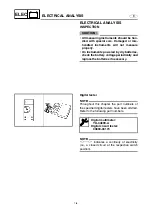
Peak voltage adapter
NOTE:
• Throughout this chapter the part number of
the peak voltage adapters have been omit-
ted. Refer to the following part numbers.
• The peak voltage adapter should be used
with the digital tester.
• When measuring the peak voltage, connect
the peak voltage adapter to the digital circuit
tester and switch the selector to the DC volt-
age mode.
NOTE:
• Make sure that the adapter leads are prop-
erly installed in the digital circuit tester.
• Make sure that the positive pin (the “+” mark
facing up as shown) on the adapter is
installed into the positive terminal of the
tester.
• The test harness is needed for the following
tests.
È
Voltage measurement
É
Peak voltage measurement
Peak volt meter adapter:
YU-39991
Peak voltage adapter B:
90890-03172
È
É
Test harness
NOTE:
If the lighting coil and pickup coil(s) are mea-
sured unloaded, disconnect the test harness
from the coupler of the output end.
Checking steps:
• Disconnect the coupler connections.
• Connect the test harness between the
couplers.
• Connect the tester terminals to the termi-
nals which are being checked.
• Run the engine and observe the mea-
surement.
Summary of Contents for WaveRunner GP1300R
Page 1: ...SUPPLEMENTARY SERVICE MANUAL GP1300R WaveRunner F1G 28197 1G 1X LIT 18616 02 90 LIT186160290...
Page 10: ...E TROUBLE ANALYSIS TROUBLE ANALYSIS 48 SELF DIAGNOSIS 48 WIRING DIAGRAM...
Page 61: ...YAMAHA MOTOR CORPORATION USA Printed in USA Dec 2004 0 0 1 CR E...
Page 62: ...SERVICE MANUAL GP1300R WaveRunner F1G 28197 1F 11 LIT 18616 02 44 LIT186160244...
Page 340: ...YAMAHA MOTOR CORPORATION USA Printed in USA Feb 2003 0 0 1 CR E...

