7-16
E
–
+
ELEC
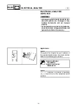
4. Measure:
• Rectifier/regulator output peak voltage
Below specification
→
Replace the recti-
fier/regulator.
NOTE:
• Do not use the peak voltage adapter to mea-
sure the output voltage.
• Disconnect the output lead of the tester har-
ness.
BATTERY
Refer to “ELECTRICAL” in Chapter 3.
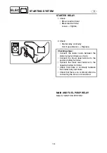
FUSE
Refer to “STARTING SYSTEM.”
SPARK PLUGS
Refer to “POWER UNIT” in Chapter 3.
SPARK PLUG LEAD ASSEMBLY
1. Check:
• Spark plug lead assembly
Cracks/damage
→
Replace.
Test harness (6 pins):
YB-06848
Test harness FSW-6A (6 pins):
90890-06848
Rectifier/regulator output peak
voltage:
Red (R) – Black (B)
r/min
Unloaded
3,500
V
14.5
2. Measure:
• Spark plug lead resistance
Out of specification
→
Replace.
Spark plug lead resistance:
#1: 6.1–14.3 k
Ω
#2: 4.5–10.9 k
Ω
#3: 3.3–8.2 k
Ω
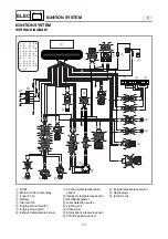
IGNITION SYSTEM
Summary of Contents for WaveRunner GP1300R
Page 1: ...SUPPLEMENTARY SERVICE MANUAL GP1300R WaveRunner F1G 28197 1G 1X LIT 18616 02 90 LIT186160290...
Page 10: ...E TROUBLE ANALYSIS TROUBLE ANALYSIS 48 SELF DIAGNOSIS 48 WIRING DIAGRAM...
Page 61: ...YAMAHA MOTOR CORPORATION USA Printed in USA Dec 2004 0 0 1 CR E...
Page 62: ...SERVICE MANUAL GP1300R WaveRunner F1G 28197 1F 11 LIT 18616 02 44 LIT186160244...
Page 340: ...YAMAHA MOTOR CORPORATION USA Printed in USA Feb 2003 0 0 1 CR E...

