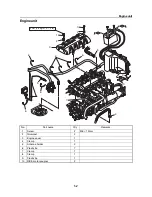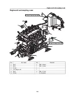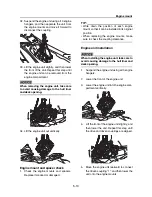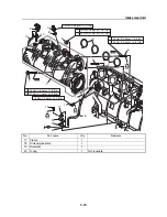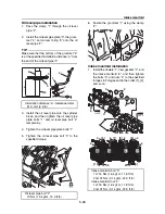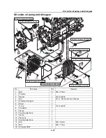
Engine mount
5-14
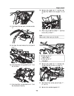
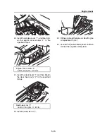
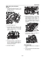
29. Fasten the wire harness using the plastic
ties “1”.
30. Connect the fuel pump module coupler “a”.
31. Fasten the wire harness using the plastic
ties “1”.
32. Connect the sensor and switch couplers
“a”. See “Coupler layout” (2-17).
33. Connect the remote control receiver cou-
pler “a”, and then fasten the wire harness
using the plastic tie “1”.
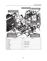
34. Install the antenna holders “2”.
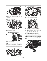
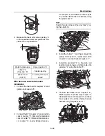
35. Install the air filter case “1”, and then tight-
en the air filter case bolts “2” to the speci-
fied torque.
36. Install the air filter, air filter case cover “3”,
and air intake pipe “4”, and then tighten the
air intake pipe clamps “5” to the specified
torque.
37. Install the breather hose “6”, and then fas-
ten it using the clamp “7”.
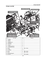
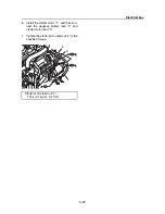
38. Connect the quick connector “1” to the fuel
rail, and then install the plastic tie “3”.
39. Install the oil level gauge “2”.
1
2
1
1
1
1
a
a
1
1
Air filter case bolt “2”
13 Nm (1.3 kgf·m, 9.6 ft·lb)
Air intake pipe clamp “5”
3.5 Nm (0.35 kgf·m, 2.58 ft·lb)
a
1
2
2
1
3
2
4
5
5
6
2
7
Summary of Contents for Waverunner VXS VX1800
Page 1: ...SERVICE MANUAL WaveRunner VXS VX1800 F2W VXR VX1800A F2W F2W 28197 ZU 11 ...
Page 12: ...How to use this manual 1 7 UP Upside YDIS Yamaha Diagnostic System Abbreviation Description ...
Page 40: ...Technical tips 1 35 MEMO ...
Page 163: ...Oil separator tank and oil pan 5 72 3 4 4 4 4 4 9 4 1 5 6 10 11 7 2 3 8 ...
Page 180: ...Crankcase connecting rod and piston 5 89 MEMO ...
Page 204: ...6 23 Intermediate housing Intermediate housing bolt 2 17 Nm 1 7 kgf m 12 5 ft lb 1 2 3 ...
Page 205: ...Intermediate housing 6 24 MEMO ...
Page 251: ...Indication system 7 44 MEMO ...
Page 278: ...8 25 Exhaust system 6 Install the band Rubber hose clamp 2 3 5 Nm 0 35 kgf m 2 58 ft lb ...
Page 290: ...Deck and hull 8 37 MEMO ...
Page 312: ...Engine unit troubleshooting 9 21 MEMO ...
Page 313: ...A Appendix Wiring diagram A 1 How to use the wiring diagram A 1 VXS VXR A 2 ...
Page 317: ......
Page 318: ...Mar 2015 CR E ...

