2
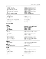
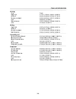
Specification
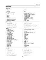
Model data .......................................................................... 2-1
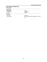
Fuel system technical data ............................................... 2-3
Fuel system ................................................................................ 2-3
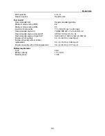
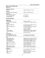
Power unit technical data .................................................. 2-4
Power unit .................................................................................. 2-4
Cylinder head ASSY................................................................... 2-4
Crankcase ASSY........................................................................ 2-5
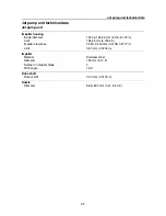
Jet pump unit technical data............................................. 2-7
Jet pump unit.............................................................................. 2-7
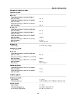
Electrical technical data .................................................... 2-8
Ignition system ........................................................................... 2-8
Charging system ........................................................................ 2-8
Control system ........................................................................... 2-8
Fuel system .............................................................................. 2-10
Starting system......................................................................... 2-10
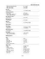
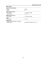
Meter system............................................................................ 2-11
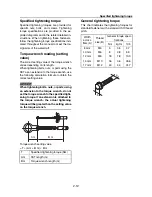
Specified tightening torque............................................. 2-12
Torque wrench reading (setting value) .......................... 2-12
General tightening torque ............................................... 2-12
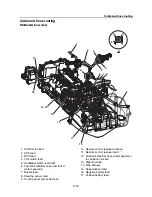
Cable and hose routing ................................................... 2-13
Starboard bow view.................................................................. 2-13
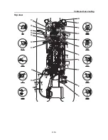
Top view ................................................................................... 2-14
Port view................................................................................... 2-16
Coupler layout .......................................................................... 2-17
Summary of Contents for Waverunner VXS VX1800
Page 1: ...SERVICE MANUAL WaveRunner VXS VX1800 F2W VXR VX1800A F2W F2W 28197 ZU 11 ...
Page 12: ...How to use this manual 1 7 UP Upside YDIS Yamaha Diagnostic System Abbreviation Description ...
Page 40: ...Technical tips 1 35 MEMO ...
Page 163: ...Oil separator tank and oil pan 5 72 3 4 4 4 4 4 9 4 1 5 6 10 11 7 2 3 8 ...
Page 180: ...Crankcase connecting rod and piston 5 89 MEMO ...
Page 204: ...6 23 Intermediate housing Intermediate housing bolt 2 17 Nm 1 7 kgf m 12 5 ft lb 1 2 3 ...
Page 205: ...Intermediate housing 6 24 MEMO ...
Page 251: ...Indication system 7 44 MEMO ...
Page 278: ...8 25 Exhaust system 6 Install the band Rubber hose clamp 2 3 5 Nm 0 35 kgf m 2 58 ft lb ...
Page 290: ...Deck and hull 8 37 MEMO ...
Page 312: ...Engine unit troubleshooting 9 21 MEMO ...
Page 313: ...A Appendix Wiring diagram A 1 How to use the wiring diagram A 1 VXS VXR A 2 ...
Page 317: ......
Page 318: ...Mar 2015 CR E ...


