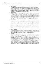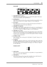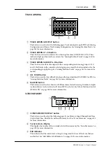
Control Surface
25
DM2000 Version 2—Owner’s Manual
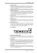
F
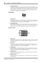
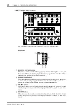
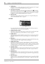
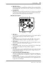
MIDI button
This button is used to select the following pages: MIDI Setup, Program Change Assign
Table, Control Change Assign Table, and Bulk Dump. See “MIDI” on page 215 for more
information.
G
METER button
This button is used to select the following pages: Input Channel Meter, Master Meter, Effect
Input/Output Meter, Effect 1-8 Input/Output Meter, Effect 1–2 Input/Output Meter, Stereo
Meter, and Metering Position. See “Metering” on page 127 for more information.
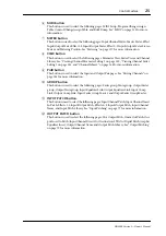
H
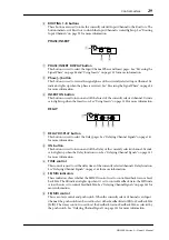
VIEW button
This button is used to select the following pages: Parameter View, Fader View, and Channel
Library. See “Viewing Channel Parameter Settings” on page 150, “Viewing Channel Fader
Settings” on page 151, and “Channel Library” on page 166 for more information.
I
PAIR button
This button is used to select the Input and Output Pair pages. See “Pairing Channels” on
page 144 for more information.
J
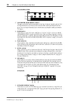
GROUP button
This button is used to select the following pages: Fader group, Mute group, Output Fader
group, Output Mute group, Input Equalizer Link, Output Equalizer Link, Input Comp
Link, Output Comp Link, Input Fader Group Master, and Output Fader Group Master.
K
INPUT PATCH button
This button is used to select the following pages: Input Channel Patch, Input Channel Insert
In Patch, Effects 1-2 Input/Output Patch, Effects 3–8 Input/Output Patch, Input Channel
Name, and Input Patch Library. See “Input Patching” on page 77 for more information.
L
OUTPUT PATCH button
This button is used to select the following pages: Slot Output Patch, Omni Out Patch, Out-
put Insert In Patch, Input Channel Direct Out Destination, 2TR Out Digital Patch, Graphic
Equalizer Insert, Output Channel Name, and Output Patch Library. See “Output Patching”
on page 79 for more information.


