62
Chapter 3—Operating Basics
DM2000 Version 2—Owner’s Manual
Assigning Parameters to the ENCODER MODE Assign Buttons
Up to four parameters can be assigned to the four ENCODER MODE ASSIGN buttons.
Initially, the following parameters are assigned to the ASSIGN buttons:
[ASSIGN 1]:
Input Patch
[ASSIGN 2]:
Direct Out
[ASSIGN 3]:
Surr. LFE Level
[ASSIGN 4]:
Surr. Pan Wheel
1
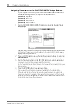
Use the ENCODER MODE [DISPLAY] button to select the Encoder Mode
Assign page.
The names of the parameters currently assigned to each ASSIGN button are displayed in the
left-hand box. The parameter currently assigned to the selected ASSIGN button appears
highlighted in the right-hand box.
2
Press an ASSIGN button, or use the Up/Down cursor buttons, to select an
ASSIGN button.
3
Use the Parameter wheel, or the INC/DEC buttons to select a parameter.
A parameter is selected when it appears inside the dotted box.
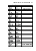
See the “Assignable Encoder Mode Parameter List” on page 63 for a complete list of assign-
able parameters.
4
Press the [ENTER] button to assign your choice.
Once assigned, the selected parameter appears highlighted in the right-hand box.
When channels that do not feature the currently assigned parameter are selected, the
Encoders are inactive. For example, if the assigned Encoder parameter is “Phase,” and the
Master Layer is selected, the Encoders are inactive, because the Bus Outs, Aux Sends, and
Matrix Sends do not feature Phase parameters.


