FUEL TANK
6-2
EAS26630
REMOVING THE FUEL TANK
1. Extract the fuel in the fuel tank through the
fuel tank cap with a pump.
2. Remove:
●
Fuel return hose
●
Fuel hose
CAUTION:
ECA14700
Although the fuel has been removed from
the fuel tank be careful when removing the
fuel hoses, since there may be fuel remain-
ing in it.
NOTE:
●
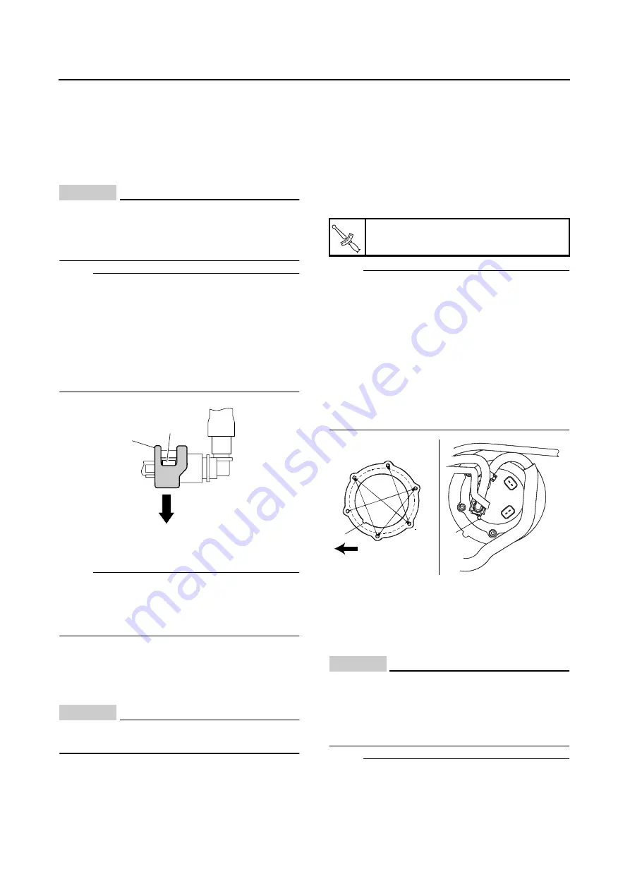
Slide the fuel hose connector cover “1” in the
direction of the arrow mark, and press the but-
tons “2” on both sides of the connector to re-
move the fuel hose.
●
Disconnecting the hose is done by hand.
There is no need to use tools.
●
Before removing the hoses, place a few rags in
the area under where it will be removed.
3. Remove:
●
Fuel tank
NOTE:
Do not set the fuel tank down so that the instal-
lation surface of the fuel pump is directly under
the tank. Be sure to lean the fuel tank in an up-
right position.
EAS26640
REMOVING THE FUEL PUMP
1. Remove:
●
Fuel pump
CAUTION:
ECA5UXB010
Do not drop the fuel pump or subject it to a
strong shock.
EAS26670
CHECKING THE FUEL PUMP BODY
1. Check:
●
Fuel pump body
Contaminants
→
Clean the fuel pump pas-
sage.
Rust/scratches/wear
→
Replace the fuel
pump assembly.
EAS26710
INSTALLING THE FUEL PUMP
1. Install:
●
Fuel pump
●
Fuel hose holders
NOTE:
●
When assembling the fuel pump, take care not
to damage the assembly surface with the fuel
tank.
●
Always use a new fuel pump gasket.
●
Face the fuel pump in the direction shown in
the illustration for assembly.
●
Align the fuel pump projection “a” with the
notch “b” in the stopper ring before assem-
bling.
●
Tighten the fuel pump bolts using the proce-
dure shown in the illustration.
EAS5UXB008
INSTALLING THE FUEL TANK
1. Install:
●
Fuel hose
●
Fuel return hose
CAUTION:
ECA14740
When installing the fuel hose, make sure that
it is securely connected, and that the fuel
hose holders are in the correct position, oth-
erwise the fuel hose will not be properly in-
stalled.
NOTE:
●
Insert the fuel hose on the fuel pipe until you
hear a definite “click “.
●
Slide the fuel hose connector cover “1” at the
1
2
Fuel pump bolts
4 Nm (0.4 m•kg, 2.9 ft•lb)
T
R
.
.
a
1
4
6
2
5
3
b
FWD
Summary of Contents for XJR1300 2007
Page 1: ...SERVICE MANUAL XJR1300 W 5WM 28197 E0 2007 ...
Page 2: ......
Page 8: ......
Page 47: ...LUBRICATION POINTS AND LUBRICANT TYPES 2 24 ...
Page 48: ...LUBRICATION DIAGRAMS 2 25 EAS28860 LUBRICATION DIAGRAMS ...
Page 50: ...LUBRICATION DIAGRAMS 2 27 ...
Page 51: ...LUBRICATION DIAGRAMS 2 28 1 Drive axle 2 Push rod 3 Main axle 4 Camshaft 5 Crankshaft ...
Page 52: ...LUBRICATION DIAGRAMS 2 29 ...
Page 53: ...LUBRICATION DIAGRAMS 2 30 1 Nozzle 2 Bypass valve 3 Oil filter element 4 Relief valve ...
Page 54: ...CABLE ROUTING 2 31 EAS20430 CABLE ROUTING ...
Page 56: ...CABLE ROUTING 2 33 ...
Page 58: ...CABLE ROUTING 2 35 ...
Page 60: ...CABLE ROUTING 2 37 ...
Page 62: ...CABLE ROUTING 2 39 ...
Page 64: ...CABLE ROUTING 2 41 ...
Page 66: ...CABLE ROUTING 2 43 ...
Page 68: ...CABLE ROUTING 2 45 ...
Page 70: ...CABLE ROUTING 2 47 ...
Page 205: ...GENERATOR 5 32 b Measure the stator coil resistances 1 2 ...
Page 240: ...STARTER CLUTCH 5 67 1 3 2 New ...
Page 260: ...FUEL TANK 6 3 fuel hose end in the direction of the arrow 1 ...
Page 269: ...THROTTLE BODIES 6 12 ...
Page 270: ...AIR INDUCTION SYSTEM 6 13 EAS27040 AIR INDUCTION SYSTEM 1 2 3 4 4 5 4 4 3 2 1 1 2 4 3 ...
Page 274: ...AIR INDUCTION SYSTEM 6 17 ...
Page 277: ......
Page 278: ...IGNITION SYSTEM 7 1 EAS27090 IGNITION SYSTEM EAS27110 CIRCUIT DIAGRAM ...
Page 282: ...ELECTRIC STARTING SYSTEM 7 5 EAS27160 ELECTRIC STARTING SYSTEM EAS27170 CIRCUIT DIAGRAM ...
Page 288: ...CHARGING SYSTEM 7 11 EAS27200 CHARGING SYSTEM EAS27210 CIRCUIT DIAGRAM ...
Page 289: ...CHARGING SYSTEM 7 12 1 Generator 2 Main switch 4 Main fuse 7 Battery ...
Page 291: ...CHARGING SYSTEM 7 14 ...
Page 292: ...LIGHTING SYSTEM 7 15 EAS27240 LIGHTING SYSTEM EAS27250 CIRCUIT DIAGRAM ...
Page 295: ...LIGHTING SYSTEM 7 18 ...
Page 296: ...SIGNALING SYSTEM 7 19 EAS27270 SIGNALING SYSTEM EAS27280 CIRCUIT DIAGRAM ...
Page 302: ...FUEL INJECTION SYSTEM 7 25 EAS27330 FUEL INJECTION SYSTEM EAS27340 CIRCUIT DIAGRAM ...
Page 342: ...FUEL PUMP SYSTEM 7 65 EAS27580 FUEL PUMP SYSTEM EAS27590 CIRCUIT DIAGRAM ...
Page 345: ...FUEL PUMP SYSTEM 7 68 ...
Page 346: ...IMMOBILIZER SYSTEM 7 69 EAS27640 IMMOBILIZER SYSTEM EAS27650 CIRCUIT DIAGRAM ...
Page 355: ...IMMOBILIZER SYSTEM 7 78 ...
Page 361: ...ELECTRICAL COMPONENTS 7 84 a b Br R Br R ...
Page 382: ......
Page 383: ......
Page 384: ...YAMAHA MOTOR CO LTD 2500 SHINGAI IWATA SHIZUOKA JAPAN ...


