FUEL INJECTION SYSTEM
7-29
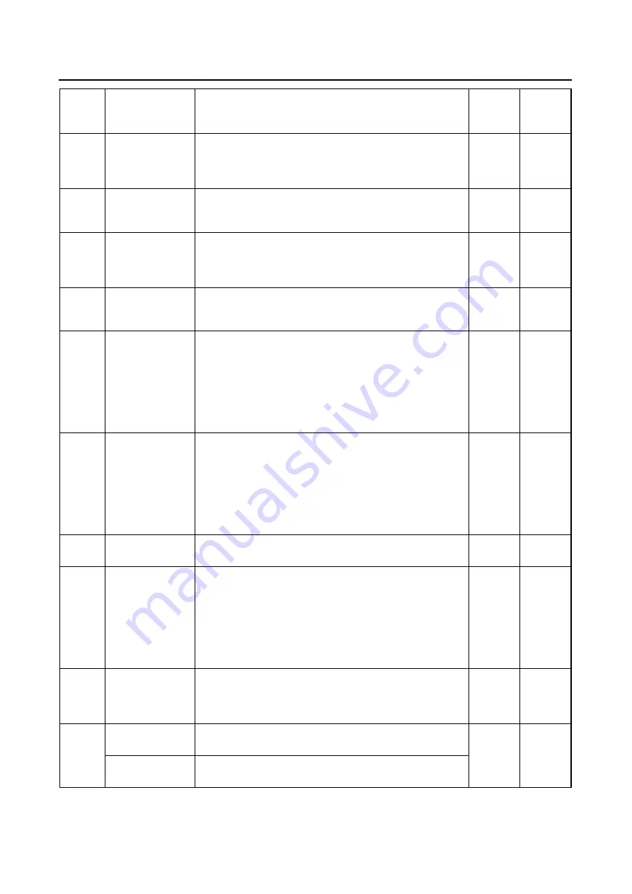
25
Intake air pres-
sure sensor 2
(open or
short-circuit)
Intake air pressure sensor-open or short circuit is
detected.
Able
Able
26
Intake air pres-
sure sensor 2
(pipe system)
Intake air pressure sensor-pipe system malfunction
(clogged or detached hose).
Able
Able
28
Engine temper-
ature sensor
(Open or
short-circuit)
Engine temperature sensor open or short circuit is
detected.
Able
Able
30
Lean angle
sensor
Latch up detected.
No normal signals received from the lean angle
sensor.
Unable
Unable
33
Ignition coil (#1
and #4)
(faulty ignition)
Malfunction detected in the primary lead of the igni-
tion coil. (#1 and #4)
Able
(depen
ding on
the
number
of faulty
cylin-
ders)
Able
(depen
ding on
the
number
of faulty
cylin-
ders)
34
Ignition coil (#2
and #3)
(faulty ignition)
Malfunction detected in the primary lead of the igni-
tion coil. (#2 and #3)
Able
(depen
ding on
the
number
of faulty
cylin-
ders)
Able
(depen
ding on
the
number
of faulty
cylin-
ders)
37
ISC (Idle speed
control) valve
Engine speed is high when the engine is idling.
Able
Able
39
Injector
Injector open or short-circuit is detected.
Able
(depen
ding on
the
number
of faulty
cylin-
ders)
Able
(depen
ding on
the
number
of faulty
cylin-
ders)
41
Lean angle
sensor
(open or
short-circuit)
Lean angle sensor open or short circuit is detected. Unable
Unable
42
Speed sensor
No normal signals are received from the speed
sensor.
Able
Able
Neutral switch
Open or short circuit is detected in the neutral
switch.
Fault
code
No.
Item
Symptom
Able /
unable to
start
Able /
unable to
drive
Summary of Contents for XJR1300 2007
Page 1: ...SERVICE MANUAL XJR1300 W 5WM 28197 E0 2007 ...
Page 2: ......
Page 8: ......
Page 47: ...LUBRICATION POINTS AND LUBRICANT TYPES 2 24 ...
Page 48: ...LUBRICATION DIAGRAMS 2 25 EAS28860 LUBRICATION DIAGRAMS ...
Page 50: ...LUBRICATION DIAGRAMS 2 27 ...
Page 51: ...LUBRICATION DIAGRAMS 2 28 1 Drive axle 2 Push rod 3 Main axle 4 Camshaft 5 Crankshaft ...
Page 52: ...LUBRICATION DIAGRAMS 2 29 ...
Page 53: ...LUBRICATION DIAGRAMS 2 30 1 Nozzle 2 Bypass valve 3 Oil filter element 4 Relief valve ...
Page 54: ...CABLE ROUTING 2 31 EAS20430 CABLE ROUTING ...
Page 56: ...CABLE ROUTING 2 33 ...
Page 58: ...CABLE ROUTING 2 35 ...
Page 60: ...CABLE ROUTING 2 37 ...
Page 62: ...CABLE ROUTING 2 39 ...
Page 64: ...CABLE ROUTING 2 41 ...
Page 66: ...CABLE ROUTING 2 43 ...
Page 68: ...CABLE ROUTING 2 45 ...
Page 70: ...CABLE ROUTING 2 47 ...
Page 205: ...GENERATOR 5 32 b Measure the stator coil resistances 1 2 ...
Page 240: ...STARTER CLUTCH 5 67 1 3 2 New ...
Page 260: ...FUEL TANK 6 3 fuel hose end in the direction of the arrow 1 ...
Page 269: ...THROTTLE BODIES 6 12 ...
Page 270: ...AIR INDUCTION SYSTEM 6 13 EAS27040 AIR INDUCTION SYSTEM 1 2 3 4 4 5 4 4 3 2 1 1 2 4 3 ...
Page 274: ...AIR INDUCTION SYSTEM 6 17 ...
Page 277: ......
Page 278: ...IGNITION SYSTEM 7 1 EAS27090 IGNITION SYSTEM EAS27110 CIRCUIT DIAGRAM ...
Page 282: ...ELECTRIC STARTING SYSTEM 7 5 EAS27160 ELECTRIC STARTING SYSTEM EAS27170 CIRCUIT DIAGRAM ...
Page 288: ...CHARGING SYSTEM 7 11 EAS27200 CHARGING SYSTEM EAS27210 CIRCUIT DIAGRAM ...
Page 289: ...CHARGING SYSTEM 7 12 1 Generator 2 Main switch 4 Main fuse 7 Battery ...
Page 291: ...CHARGING SYSTEM 7 14 ...
Page 292: ...LIGHTING SYSTEM 7 15 EAS27240 LIGHTING SYSTEM EAS27250 CIRCUIT DIAGRAM ...
Page 295: ...LIGHTING SYSTEM 7 18 ...
Page 296: ...SIGNALING SYSTEM 7 19 EAS27270 SIGNALING SYSTEM EAS27280 CIRCUIT DIAGRAM ...
Page 302: ...FUEL INJECTION SYSTEM 7 25 EAS27330 FUEL INJECTION SYSTEM EAS27340 CIRCUIT DIAGRAM ...
Page 342: ...FUEL PUMP SYSTEM 7 65 EAS27580 FUEL PUMP SYSTEM EAS27590 CIRCUIT DIAGRAM ...
Page 345: ...FUEL PUMP SYSTEM 7 68 ...
Page 346: ...IMMOBILIZER SYSTEM 7 69 EAS27640 IMMOBILIZER SYSTEM EAS27650 CIRCUIT DIAGRAM ...
Page 355: ...IMMOBILIZER SYSTEM 7 78 ...
Page 361: ...ELECTRICAL COMPONENTS 7 84 a b Br R Br R ...
Page 382: ......
Page 383: ......
Page 384: ...YAMAHA MOTOR CO LTD 2500 SHINGAI IWATA SHIZUOKA JAPAN ...


