ELECTRICAL COMPONENTS
7-87
4. Install:
●
SEAT
Refer to “GENERAL CHASSIS” on page 4-1.
EAS28030
CHECKING AND CHARGING THE BATTERY
WARNING
EWA5UXB006
Batteries generate explosive hydrogen gas
and contain electrolyte which is made of poi-
sonous and highly caustic sulfuric acid.
Therefore, always follow these preventive
measures:
●
Wear protective eye gear when handling or
working near batteries.
●
Charge batteries in a well-ventilated area.
●
Keep batteries away from fire, sparks or
open flames (e.g., welding equipment,
lighted cigarettes).
●
DO NOT SMOKE when charging or han-
dling batteries.
●
KEEP BATTERIES AND ELECTROLYTE
OUT OF REACH OF CHILDREN.
●
Avoid bodily contact with electrolyte as it
can cause severe burns or permanent eye
injury.
FIRST AID IN CASE OF BODILY CONTACT:
EXTERNAL
●
Skin — Wash with water.
●
Eyes — Flush with water for 15 minutes and
get immediate medical attention.
INTERNAL
●
Drink large quantities of water or milk fol-
lowed with milk of magnesia, beaten egg or
vegetable oil. Get immediate medical atten-
tion.
CAUTION:
ECA5UXB012
●
This is a sealed battery. Never remove the
sealing caps because the balance between
cells will not be maintained and battery per-
formance will deteriorate.
●
Charging time, charging amperage and
charging voltage for an MF battery are dif-
ferent from those of conventional batteries.
The MF battery should be charged as ex-
plained in the charging method illustra-
tions. If the battery is overcharged, the
electrolyte level will drop considerably.
Therefore, take special care when charging
the battery.
NOTE:
Since MF batteries are sealed, it is not possible
to check the charge state of the battery by mea-
suring the specific gravity of the electrolyte.
Therefore, the charge of the battery has to be
checked by measuring the voltage at the battery
terminals.
1. Remove:
●
SEAT
Refer to “GENERAL CHASSIS” on page 4-1.
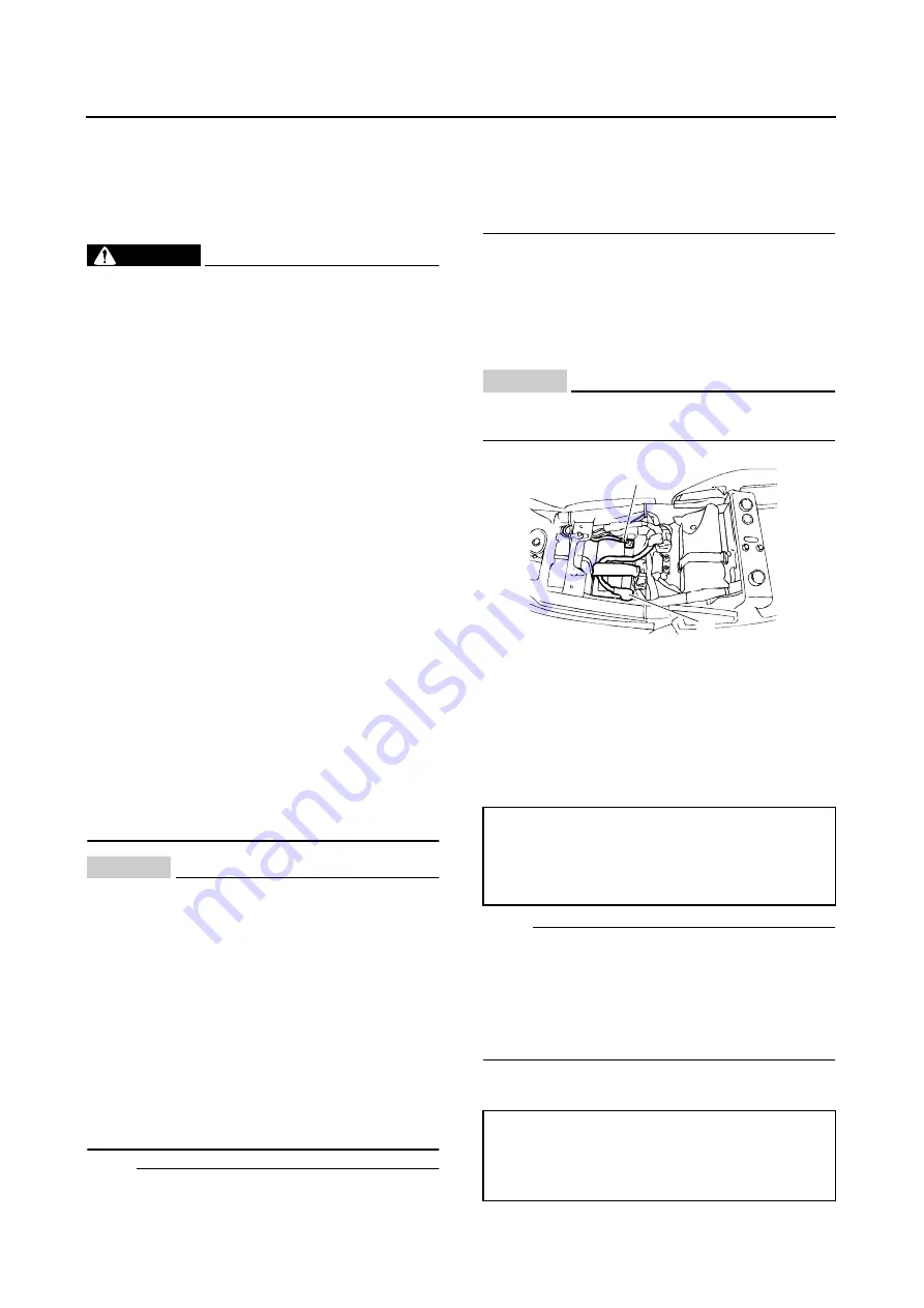
2. Disconnect:
●
Battery leads
(from the battery terminals)
CAUTION:
ECA13640
First, disconnect the negative battery lead
“1”, and then positive battery lead “2”.
3. Remove:
●
Battery
4. Check:
●
Battery terminal voltage
▼▼▼▼▼▼▼▼▼▼▼▼▼▼▼▼▼▼▼▼▼▼▼▼▼▼▼▼▼▼▼▼
a. Connect a pocket tester to the battery termi-
nals.
NOTE:
●
The charge state of an MF battery can be
checked by measuring its open-circuit voltage
(i.e., the voltage when the positive battery ter-
minal is disconnected).
●
No charging is necessary when the open-cir-
cuit voltage equals or exceeds 12.8 V.
b. Check the charge of the battery, as shown in
the charts and the following example.
Positive tester probe
→
→
→
→
positive battery
terminal
Negative tester probe
→
→
→
→
negative battery
terminal
Example
Open-circuit voltage = 12.0 V
Charging time = 6.5 hours
Charge of the battery = 20
–
30%
2
1
Summary of Contents for XJR1300 2007
Page 1: ...SERVICE MANUAL XJR1300 W 5WM 28197 E0 2007 ...
Page 2: ......
Page 8: ......
Page 47: ...LUBRICATION POINTS AND LUBRICANT TYPES 2 24 ...
Page 48: ...LUBRICATION DIAGRAMS 2 25 EAS28860 LUBRICATION DIAGRAMS ...
Page 50: ...LUBRICATION DIAGRAMS 2 27 ...
Page 51: ...LUBRICATION DIAGRAMS 2 28 1 Drive axle 2 Push rod 3 Main axle 4 Camshaft 5 Crankshaft ...
Page 52: ...LUBRICATION DIAGRAMS 2 29 ...
Page 53: ...LUBRICATION DIAGRAMS 2 30 1 Nozzle 2 Bypass valve 3 Oil filter element 4 Relief valve ...
Page 54: ...CABLE ROUTING 2 31 EAS20430 CABLE ROUTING ...
Page 56: ...CABLE ROUTING 2 33 ...
Page 58: ...CABLE ROUTING 2 35 ...
Page 60: ...CABLE ROUTING 2 37 ...
Page 62: ...CABLE ROUTING 2 39 ...
Page 64: ...CABLE ROUTING 2 41 ...
Page 66: ...CABLE ROUTING 2 43 ...
Page 68: ...CABLE ROUTING 2 45 ...
Page 70: ...CABLE ROUTING 2 47 ...
Page 205: ...GENERATOR 5 32 b Measure the stator coil resistances 1 2 ...
Page 240: ...STARTER CLUTCH 5 67 1 3 2 New ...
Page 260: ...FUEL TANK 6 3 fuel hose end in the direction of the arrow 1 ...
Page 269: ...THROTTLE BODIES 6 12 ...
Page 270: ...AIR INDUCTION SYSTEM 6 13 EAS27040 AIR INDUCTION SYSTEM 1 2 3 4 4 5 4 4 3 2 1 1 2 4 3 ...
Page 274: ...AIR INDUCTION SYSTEM 6 17 ...
Page 277: ......
Page 278: ...IGNITION SYSTEM 7 1 EAS27090 IGNITION SYSTEM EAS27110 CIRCUIT DIAGRAM ...
Page 282: ...ELECTRIC STARTING SYSTEM 7 5 EAS27160 ELECTRIC STARTING SYSTEM EAS27170 CIRCUIT DIAGRAM ...
Page 288: ...CHARGING SYSTEM 7 11 EAS27200 CHARGING SYSTEM EAS27210 CIRCUIT DIAGRAM ...
Page 289: ...CHARGING SYSTEM 7 12 1 Generator 2 Main switch 4 Main fuse 7 Battery ...
Page 291: ...CHARGING SYSTEM 7 14 ...
Page 292: ...LIGHTING SYSTEM 7 15 EAS27240 LIGHTING SYSTEM EAS27250 CIRCUIT DIAGRAM ...
Page 295: ...LIGHTING SYSTEM 7 18 ...
Page 296: ...SIGNALING SYSTEM 7 19 EAS27270 SIGNALING SYSTEM EAS27280 CIRCUIT DIAGRAM ...
Page 302: ...FUEL INJECTION SYSTEM 7 25 EAS27330 FUEL INJECTION SYSTEM EAS27340 CIRCUIT DIAGRAM ...
Page 342: ...FUEL PUMP SYSTEM 7 65 EAS27580 FUEL PUMP SYSTEM EAS27590 CIRCUIT DIAGRAM ...
Page 345: ...FUEL PUMP SYSTEM 7 68 ...
Page 346: ...IMMOBILIZER SYSTEM 7 69 EAS27640 IMMOBILIZER SYSTEM EAS27650 CIRCUIT DIAGRAM ...
Page 355: ...IMMOBILIZER SYSTEM 7 78 ...
Page 361: ...ELECTRICAL COMPONENTS 7 84 a b Br R Br R ...
Page 382: ......
Page 383: ......
Page 384: ...YAMAHA MOTOR CO LTD 2500 SHINGAI IWATA SHIZUOKA JAPAN ...


