2 - 77
SPEC
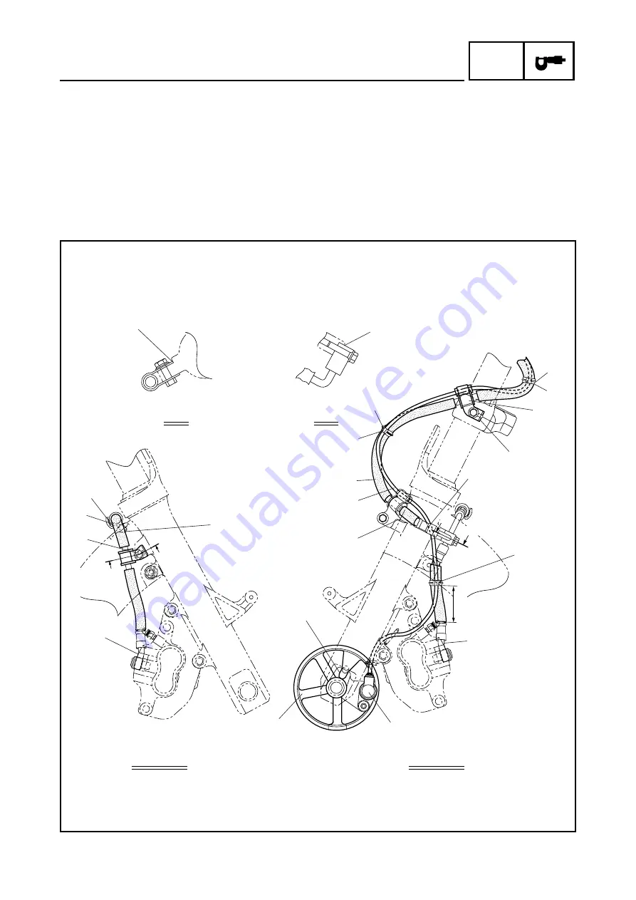
CABLE ROUTING
Í
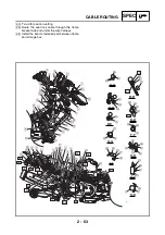
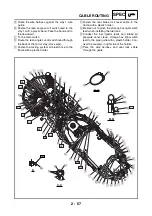
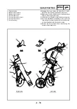
Install the stopper to lower bracket projection.
Î
Fasten the front wheel sensor lead to the center
of brake hose holder.
Ï
Fasten the front wheel sensor lead along the
outside of the brake hose.
Ð
Pass the front wheel sensor lead between the
brake hose and front fork.
Ñ
Make sure that the stopper touches the outer
tube stay.
Ò
30 ~ 40 mm (1.18 ~ 1.57 in)
Ó
Make sure that brake pipe touches the projec-
tion.
Ô
Make sure that the slot in the sensor housing fits
stopper on the outer tube.
Õ
Make sure that the brake hose holder touches
the projection of the outer tube.
Ö
Make sure that the brake hose joint touches the
projection of the outer tube.
B-B
A-A
A
A
B
B
Ì
Ë
Í
Î
Ï
Ð
Ñ
Ï
Ò
Ó
Ô
È
É
Ê
1
2
Õ
Ö
3
4
5
6
7
Right side
Left side
Summary of Contents for XP500
Page 1: ...2005 XP500 XP500A5VU5 AE1 SERVICE MANUAL...
Page 2: ......
Page 8: ......
Page 9: ...GEN INFO 1...
Page 11: ...GEN INFO...
Page 38: ...SPEC 2...
Page 40: ...SPEC...
Page 68: ...2 28 SPEC OIL FLOW DIAGRAMS 1 Oil strainer 2 Crankshaft...
Page 69: ...2 29 SPEC OIL FLOW DIAGRAMS 1 Clutch 2 Right main journal bearing 3 Main gallery plug...
Page 118: ......
Page 119: ...CHK ADJ 3...
Page 193: ......
Page 194: ...CHAS 4...
Page 198: ...CHAS...
Page 292: ...4 94 CHAS ANTI LOCK BRAKE SYSTEM XP500A...
Page 326: ......
Page 327: ...ENG 5...
Page 331: ...ENG...
Page 424: ...COOL 6...
Page 426: ...COOL...
Page 442: ......
Page 443: ...FI 7...
Page 445: ...FI...
Page 476: ...ELEC 8...
Page 544: ......
Page 545: ...TRBL SHTG 9...
Page 553: ......
Page 556: ......
Page 557: ...YAMAHA MOTOR CO LTD 2500 SHINGAI IWATA SHIZUOKA JAPAN...

