1 - 11
GEN
INFO
FEATURES
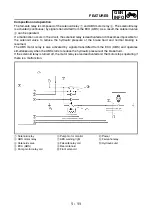
Composition and operation
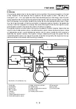
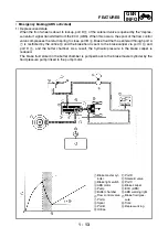
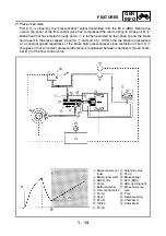
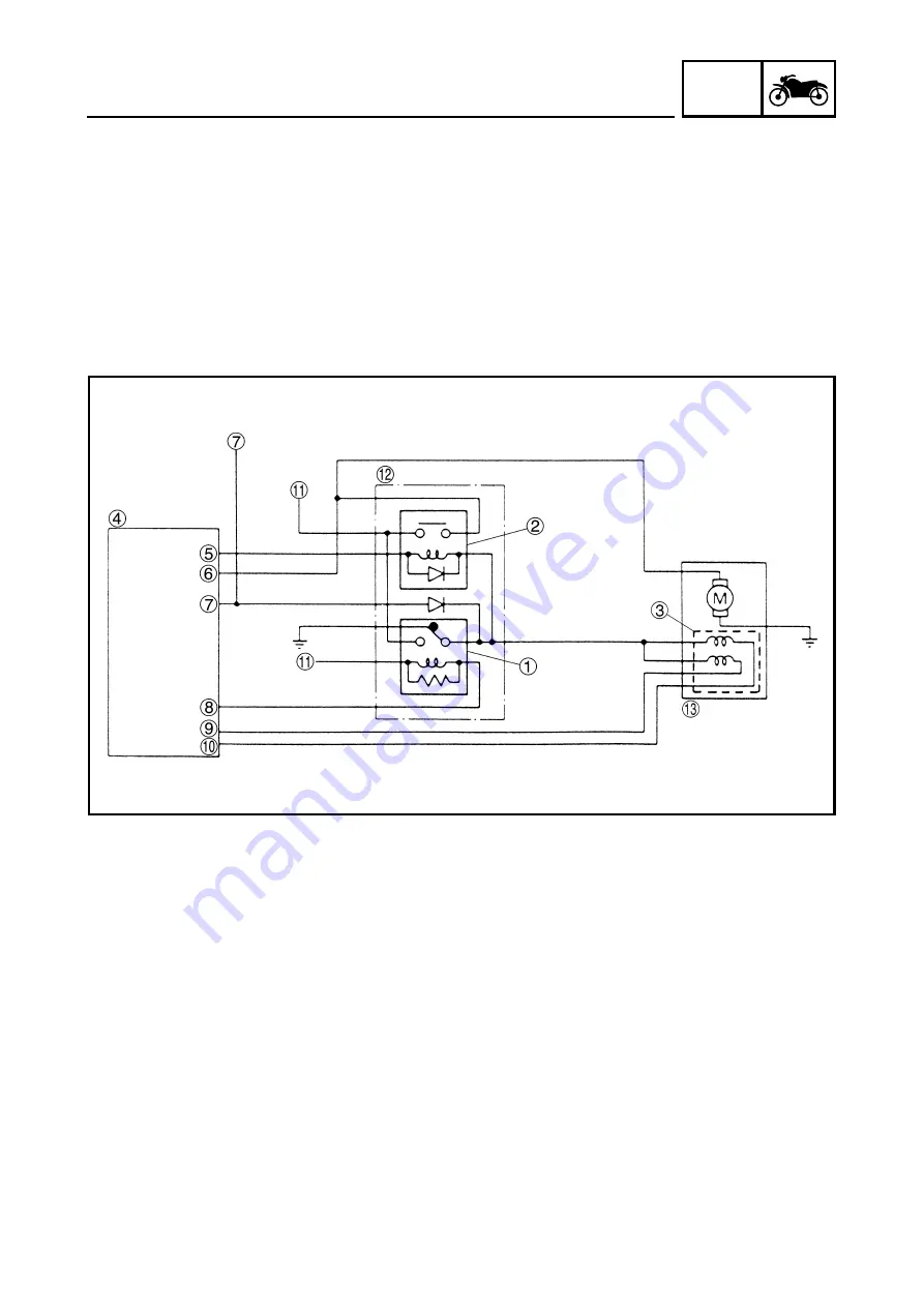
The fail-safe relay is composed of the solenoid relay
1
and ABS motor relay
2
. The solenoid relay
is activated (continuous) by signals transmitted from the ECU (ABS). As a result, the solenoid valve
3
can be operated.
If a malfunction occurs in the circuit, the solenoid relay is deactivated and it becomes impossible for
the solenoid valve to reduce the hydraulic pressure of the brake fluid and normal braking is
resumed.
The ABS motor relay is also activated by signals transmitted from the ECU (ABS) and operates
simultaneously when the ABS starts to reduce the hydraulic pressure of the brake fluid.
If the solenoid relay is turned off, the motor relay is also deactivated and the motor stops operating if
there is a malfunction.
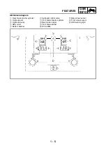
1
Solenoid relay
2
ABS motor relay
3
Solenoid valve
4
ECU (ABS)
5
Pump motor relay coil
6
Pump motor monitor
7
ABS warning light
8
Fail-safe relay coil
9
Rear solenoid
0
Front solenoid
A
Power
B
Fail-safe relay
C
Hydraulic unit
Summary of Contents for XP500
Page 1: ...2005 XP500 XP500A5VU5 AE1 SERVICE MANUAL...
Page 2: ......
Page 8: ......
Page 9: ...GEN INFO 1...
Page 11: ...GEN INFO...
Page 38: ...SPEC 2...
Page 40: ...SPEC...
Page 68: ...2 28 SPEC OIL FLOW DIAGRAMS 1 Oil strainer 2 Crankshaft...
Page 69: ...2 29 SPEC OIL FLOW DIAGRAMS 1 Clutch 2 Right main journal bearing 3 Main gallery plug...
Page 118: ......
Page 119: ...CHK ADJ 3...
Page 193: ......
Page 194: ...CHAS 4...
Page 198: ...CHAS...
Page 292: ...4 94 CHAS ANTI LOCK BRAKE SYSTEM XP500A...
Page 326: ......
Page 327: ...ENG 5...
Page 331: ...ENG...
Page 424: ...COOL 6...
Page 426: ...COOL...
Page 442: ......
Page 443: ...FI 7...
Page 445: ...FI...
Page 476: ...ELEC 8...
Page 544: ......
Page 545: ...TRBL SHTG 9...
Page 553: ......
Page 556: ......
Page 557: ...YAMAHA MOTOR CO LTD 2500 SHINGAI IWATA SHIZUOKA JAPAN...


