1 - 16
GEN
INFO
FEATURES
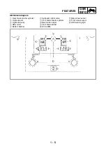
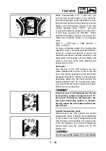
When approximately 2.8 L (0.62 Imp gal,
0.74 US gal) of fuel remains in the fuel tank,
the bottom segment of the fuel meter and fuel
level warning symbol will start flashing, and the
display will automatically change to the fuel
reserve tripmeter mode “TRIP F” and start
counting the distance traveled from that point.
In that case, pushing the “SELECT” button
switches the display between the various trip-
meter and odometer modes in the following
order:
TRIP F
→
TRIP (top)
→
TRIP (bottom)
→
ODO
→
TRIP F
To reset a tripmeter, select it by pushing the
“SELECT” button, and then push the “RESET”
button for at least one second. If you do not
reset the fuel reserve tripmeter manually, it will
reset itself automatically and the display will
return to the prior mode after refueling and
traveling 5 km (3 mi).
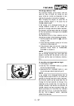
Fuel meter
With the key in the “ON” position, the fuel
meter indicates the amount of fuel in the fuel
tank. The display segments of the fuel meter
disappear towards “E” (Empty) as the fuel level
decreases. When the fuel level reaches the
bottom segment near “E”, the fuel level warn-
ing symbol and the bottom segment will flash.
Refuel as soon as possible.
CAUTION:
If the fuel level is not displayed and the fuel
level warning symbol, triangular mark, “E”
line and “F” line flash in the fuel meter, the
fuel level monitoring system is malfunc-
tioning. Check the fuel sender and the elec-
trical circuit.
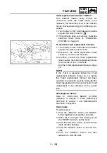
Coolant temperature meter
With the key in the “ON” position, the coolant
temperature meter indicates the temperature
of the coolant. The coolant temperature varies
with changes in the weather and engine load.
If the top segment and coolant temperature
symbol flash, stop the vehicle and let the
engine cool.
CAUTION:
Do not operate the engine if it is overheated.
Summary of Contents for XP500
Page 1: ...2005 XP500 XP500A5VU5 AE1 SERVICE MANUAL...
Page 2: ......
Page 8: ......
Page 9: ...GEN INFO 1...
Page 11: ...GEN INFO...
Page 38: ...SPEC 2...
Page 40: ...SPEC...
Page 68: ...2 28 SPEC OIL FLOW DIAGRAMS 1 Oil strainer 2 Crankshaft...
Page 69: ...2 29 SPEC OIL FLOW DIAGRAMS 1 Clutch 2 Right main journal bearing 3 Main gallery plug...
Page 118: ......
Page 119: ...CHK ADJ 3...
Page 193: ......
Page 194: ...CHAS 4...
Page 198: ...CHAS...
Page 292: ...4 94 CHAS ANTI LOCK BRAKE SYSTEM XP500A...
Page 326: ......
Page 327: ...ENG 5...
Page 331: ...ENG...
Page 424: ...COOL 6...
Page 426: ...COOL...
Page 442: ......
Page 443: ...FI 7...
Page 445: ...FI...
Page 476: ...ELEC 8...
Page 544: ......
Page 545: ...TRBL SHTG 9...
Page 553: ......
Page 556: ......
Page 557: ...YAMAHA MOTOR CO LTD 2500 SHINGAI IWATA SHIZUOKA JAPAN...

