5 - 23
ENG
VALVES AND VALVE SPRINGS
▼▼▼
▼
▼ ▼▼▼
▼
▼ ▼▼▼
▼
▼ ▼▼▼
▼
▼ ▼▼▼
▼
▼ ▼▼▼
▼
▼▼▼
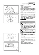
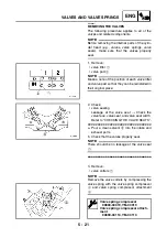
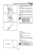
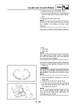
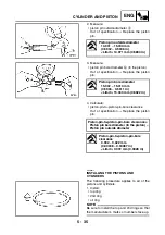
a. Remove the valve guide with a valve guide
remover
1
.
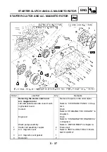
b. Install the new valve guide with a valve
guide installer
2
and valve guide remover
1
.
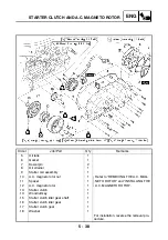
c. After installing the valve guide, bore the
valve guide with a valve guide reamer
3
to
obtain the proper valve-stem-to-valve-guide
clearance.
NOTE:
After replacing the valve guide, reface the
valve seat.
▲▲▲
▲
▲ ▲▲▲
▲
▲ ▲▲▲
▲
▲ ▲▲▲
▲
▲ ▲▲▲
▲
▲ ▲▲▲
▲
▲▲▲
Valve guide remover (4 mm)
90890-04111, YM-04111
Valve guide installer (4 mm)
90890-04112, YM-04112
Valve guide reamer (4 mm)
90890-04113, YM-04113
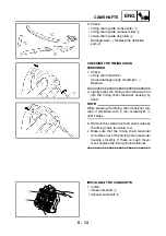
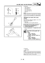
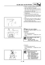
3. Eliminate:
• carbon deposits
(from the valve face and valve seat)
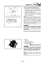
4. Check:
• valve face
Pitting/wear
→
Grind the valve face.
• valve stem end
Mushroom shape or diameter larger than
the body of the valve stem
→
Replace the
valve.
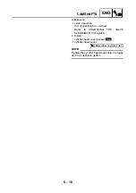
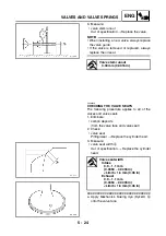
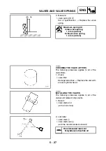
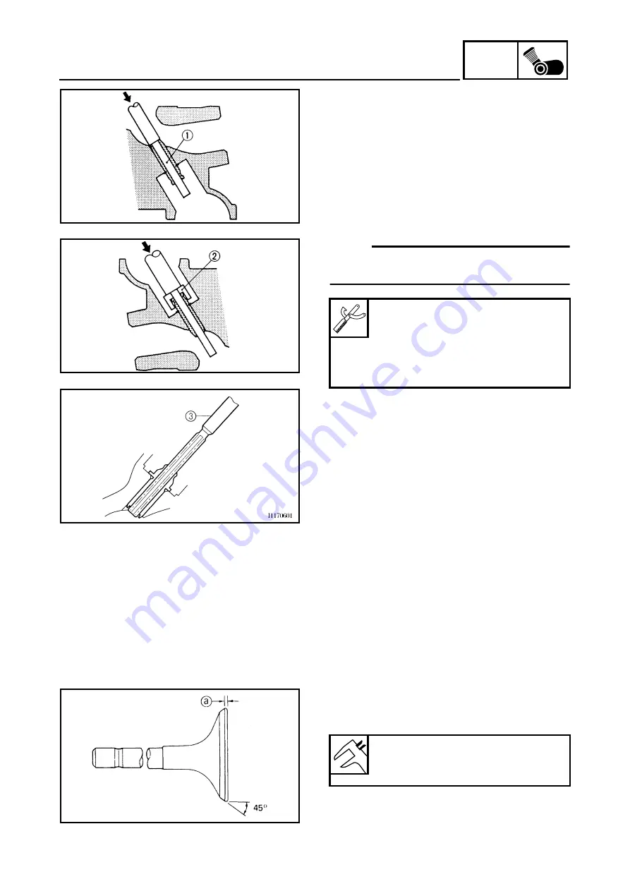
5. Measure:
• valve margin thickness
a
Out of specification
→
Replace the valve.
Valve margin thickness
0.6 ~ 0.8 mm (0.0236 ~ 0.0315 in)
<Limit>: 0.5 mm (0.0197 in)
Summary of Contents for XP500
Page 1: ...2005 XP500 XP500A5VU5 AE1 SERVICE MANUAL...
Page 2: ......
Page 8: ......
Page 9: ...GEN INFO 1...
Page 11: ...GEN INFO...
Page 38: ...SPEC 2...
Page 40: ...SPEC...
Page 68: ...2 28 SPEC OIL FLOW DIAGRAMS 1 Oil strainer 2 Crankshaft...
Page 69: ...2 29 SPEC OIL FLOW DIAGRAMS 1 Clutch 2 Right main journal bearing 3 Main gallery plug...
Page 118: ......
Page 119: ...CHK ADJ 3...
Page 193: ......
Page 194: ...CHAS 4...
Page 198: ...CHAS...
Page 292: ...4 94 CHAS ANTI LOCK BRAKE SYSTEM XP500A...
Page 326: ......
Page 327: ...ENG 5...
Page 331: ...ENG...
Page 424: ...COOL 6...
Page 426: ...COOL...
Page 442: ......
Page 443: ...FI 7...
Page 445: ...FI...
Page 476: ...ELEC 8...
Page 544: ......
Page 545: ...TRBL SHTG 9...
Page 553: ......
Page 556: ......
Page 557: ...YAMAHA MOTOR CO LTD 2500 SHINGAI IWATA SHIZUOKA JAPAN...

