5 - 32
ENG
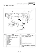
CYLINDER AND PISTON
EAS00256
CHECKING THE CYLINDERS AND
PISTONS
The following procedure applies to all of the
cylinders and pistons.
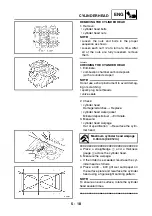
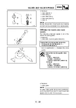
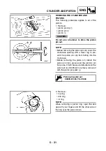
1. Check:
• piston wall
• cylinder wall
Vertical scratches
→
Rebore or replace the
cylinder, and replace the piston and piston
rings as a set.
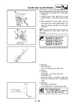
2. Measure:
• piston-to-cylinder clearance
▼▼▼
▼
▼ ▼▼▼
▼
▼ ▼▼▼
▼
▼ ▼▼▼
▼
▼ ▼▼▼
▼
▼ ▼▼▼
▼
▼▼▼
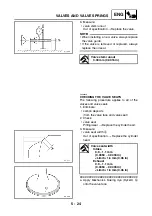
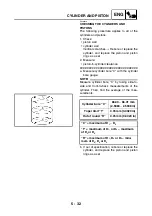
a. Measure cylinder bore “C” with the cylinder
bore gauge.
NOTE:
_
Measure cylinder bore “C” by taking side-to-
side and front-to-back measurements of the
cylinder. Then, find the average of the mea-
surements.
b. If out of specification, rebore or replace the
cylinder, and replace the piston and piston
rings as a set.
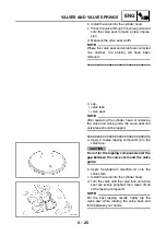
Cylinder bore “C”
66.00 ~ 66.01 mm
(2.5984 ~ 2.5988 in)
Taper limit “T”
0.05 mm (0.0020 in)
Out of round “R”
0.05 mm (0.0020 in)
“C” = maximum of D
1
~ D
6
“T” = maximum of D
1
, or D
2
– maximum
of D
5
or D
6
“R” = maximum of D
1
, D
3
or D
5
– mini-
mum of D
2
, D
4
or D
6
Summary of Contents for XP500
Page 1: ...2005 XP500 XP500A5VU5 AE1 SERVICE MANUAL...
Page 2: ......
Page 8: ......
Page 9: ...GEN INFO 1...
Page 11: ...GEN INFO...
Page 38: ...SPEC 2...
Page 40: ...SPEC...
Page 68: ...2 28 SPEC OIL FLOW DIAGRAMS 1 Oil strainer 2 Crankshaft...
Page 69: ...2 29 SPEC OIL FLOW DIAGRAMS 1 Clutch 2 Right main journal bearing 3 Main gallery plug...
Page 118: ......
Page 119: ...CHK ADJ 3...
Page 193: ......
Page 194: ...CHAS 4...
Page 198: ...CHAS...
Page 292: ...4 94 CHAS ANTI LOCK BRAKE SYSTEM XP500A...
Page 326: ......
Page 327: ...ENG 5...
Page 331: ...ENG...
Page 424: ...COOL 6...
Page 426: ...COOL...
Page 442: ......
Page 443: ...FI 7...
Page 445: ...FI...
Page 476: ...ELEC 8...
Page 544: ......
Page 545: ...TRBL SHTG 9...
Page 553: ......
Page 556: ......
Page 557: ...YAMAHA MOTOR CO LTD 2500 SHINGAI IWATA SHIZUOKA JAPAN...

