5 - 75
ENG
CRANKCASE AND CRANKSHAFT
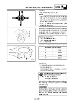
2. Check:
• crankshaft journal surfaces
• crankshaft pin surfaces
• bearing surfaces
Scratches/wear
→
Replace the crankshaft.
3. Measure:
• crankshaft-pin-to-big-end-bearing clear-
ance
Out of specification
→
Replace the big end
bearings.
▼▼▼
▼
▼ ▼▼▼
▼
▼ ▼▼▼
▼
▼ ▼▼▼
▼
▼ ▼▼▼
▼
▼ ▼▼▼
▼
▼▼▼
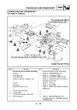
The following procedure applies to all of the
connecting rods.
CAUTION:
Do not interchange the big end bearings
and connecting rods. To obtain the correct
crankshaft-pin-to-big-end-bearing clear-
ance and prevent engine damage, the big
end bearings must be installed in their orig-
inal positions.
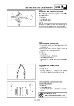
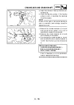
a. Clean the big end bearings, crankshaft pins
and the inside of the connecting rod halves.
b. Install the big end upper bearing into the
connecting rod and the big end lower bear-
ing into the connecting rod cap.
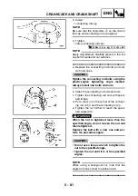
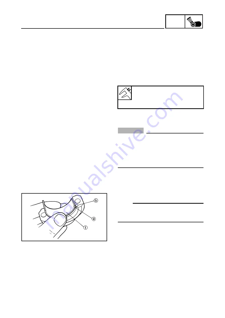
NOTE:
Align the projections
a
on the big end bear-
ings
1
with the notches
b
in the connecting
rod and connecting rod cap.
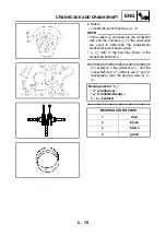
c. Put a piece of Plastigauge
®
on the crank-
shaft pin.
Crankshaft-pin-to-big-end-bear-
ing clearance
0.026 ~ 0.050 mm
(0.0010 ~ 0.0020 in)
Summary of Contents for XP500
Page 1: ...2005 XP500 XP500A5VU5 AE1 SERVICE MANUAL...
Page 2: ......
Page 8: ......
Page 9: ...GEN INFO 1...
Page 11: ...GEN INFO...
Page 38: ...SPEC 2...
Page 40: ...SPEC...
Page 68: ...2 28 SPEC OIL FLOW DIAGRAMS 1 Oil strainer 2 Crankshaft...
Page 69: ...2 29 SPEC OIL FLOW DIAGRAMS 1 Clutch 2 Right main journal bearing 3 Main gallery plug...
Page 118: ......
Page 119: ...CHK ADJ 3...
Page 193: ......
Page 194: ...CHAS 4...
Page 198: ...CHAS...
Page 292: ...4 94 CHAS ANTI LOCK BRAKE SYSTEM XP500A...
Page 326: ......
Page 327: ...ENG 5...
Page 331: ...ENG...
Page 424: ...COOL 6...
Page 426: ...COOL...
Page 442: ......
Page 443: ...FI 7...
Page 445: ...FI...
Page 476: ...ELEC 8...
Page 544: ......
Page 545: ...TRBL SHTG 9...
Page 553: ......
Page 556: ......
Page 557: ...YAMAHA MOTOR CO LTD 2500 SHINGAI IWATA SHIZUOKA JAPAN...

