CABLE ROUTING
2-30
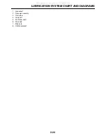
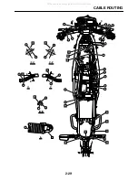
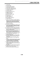
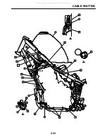
1. Clutch cable
2. Front brake hose
3. Front brake light switch lead
4. Right handlebar switch lead
5. Throttle cable (decelerator cable)
6. Throttle cable (accelerator cable)
7. Carburetor warmer lead
8. Starter motor lead
9. Rear brake light switch lead
10. Negative battery lead
11. Tail/brake light lead/
12. Rear turn signal light leads
13. Thermo switch
14. Rectifier/regulator lead
15. Clutch switch lead
16. Left handlebar switch lead
17. Rectifier/regulator
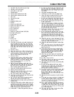
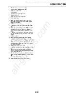
A. Enter two wire harnesses from the opening of
frame cross tube, pass them through the inside
of the vehicle, and secure them using plastic
locking tie. Face the cable tie end backwards
away from the frame cross tube, and cut off the
excess end of the tie.
B. Less than 2 mm (0.08 in)
C. Clamp rear turn signal light leads (left and right)
and tail/brake light leads using plastic locking
tie. Face the cable tie end outwards and cut off
the excess end of the tie.
D. Install each lead under the frame without slack.
E. Secure the rear turn signal light leads (left and
right) and tail/brake light leads with clamp. Face
the clamp opening upwards.
F. Secure the rear left turn signal light lead to the
end of rear fender bracket (soldered to the
frame) using plastic locking ties. Face the cable
tie end backward, and cut off the excess end of
the tie if longer than 3 mm (0.12 in).
G. Install the left rear turn signal light lead under
the frame without slack.
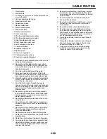
H. Secure the thermo switch lead, rectifier/regula-
tor lead, and rectifier/regulator ground lead
using clamps.
I. Secure the wire harness to the T-stud of the
frame.
J. Clamp the clutch cable, throttle cable (accelera-
tor cable), and throttle cable (decelerator cable)
using plastic locking tie. Face the tied end
inward, and cut off the excess end of the tie.
K. Route the clutch cable between the throttle
cable (accelerator cable) and the throttle cable
(decelerator cable).
L. Install the rectifier/regulator lead in horizontal to
the vehicle.
M. Clamp the plastic locking tie onto the bends of
handle as shown in the illustration.
N. Face the plastic locking tie end downwards.
All manuals and user guides at all-guides.com
Summary of Contents for XT250X 2008
Page 2: ...All manuals and user guides at all guides com...
Page 8: ...All manuals and user guides at all guides com...
Page 54: ...CABLE ROUTING 2 35 All manuals and user guides at all guides com...
Page 82: ...ELECTRICAL SYSTEM 3 27 a b All manuals and user guides at all guides com...
Page 170: ...VALVES AND VALVE SPRINGS 5 24 All manuals and user guides at all guides com...
Page 224: ...AIR INDUCTION SYSTEM 6 13 All manuals and user guides at all guides com...
Page 239: ...CHARGING SYSTEM 7 14 All manuals and user guides at all guides com...
Page 243: ...LIGHTING SYSTEM 7 18 All manuals and user guides at all guides com...
Page 249: ...SIGNALING SYSTEM 7 24 All manuals and user guides at all guides com...
Page 253: ...CARBURETOR HEATING SYSTEM 7 28 All manuals and user guides at all guides com...
Page 279: ...All manuals and user guides at all guides com...

