6*4 Frame, suspension and final drive
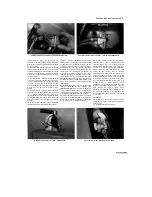
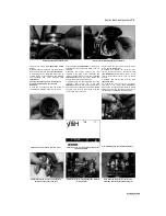
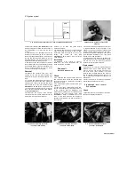
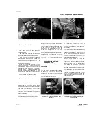
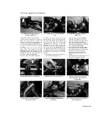
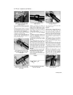
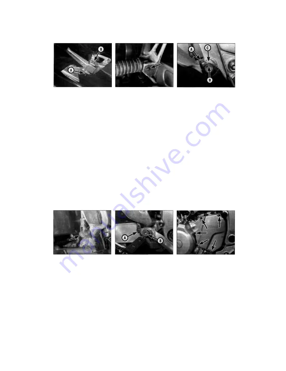
3.6 Unscrew the nut (A) and withdraw the
bolt (B)
3.7 Remove the split pin (arrowed) and
withdraw the pivot pin
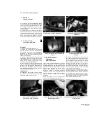
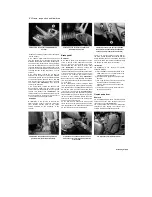
3.9a Remove the pinch bolt (A) and slide
the pedal off the shaft. Note the alignment
of the punch mark (B) with the notch (C)
renewed by removing the two screws that secure
it to the footrest.
5 On 1996-on TDM models, unscrew the nut
from the bottom of the footrest pivot bolt, then
withdraw the bolt and remove the footrest. Note
the fitting of the detent plates, ball and spring,
and take care that they do not spring out when
removing the footrest. Also note the collar for the
pivot bolt. The footrest rubber can be renewed by
removing the two screws that secure it to the
footrest.
6 On TRX models, unscrew the nut from the
bottom of the footrest pivot bolt, then withdraw
the bolt and remove the footrest. Note the fitting
of the detent plates, ball and spring, and take
care that they do not spring out when removing
the footrest
(see illustration).
Also note the
collar for the pivot bolt.
7 On XTZ models, remove the split pin and
washer (where fitted) from the bottom of the
footrest pivot pin, then withdraw the pivot pin and
remove the footrest (see
illustration).
The
footrest rubber can be renewed by removing the
washer and drawing the rubber off the footrest. If
it is stuck fast, slit it with a sharp knife.
Installation
8
Installation is the reverse of removal. On
TDM and TRX models, if removed, tighten the
front footrest bracket bolts to the torque
setting specified at the beginning of the
chapter.
Brake pedal
Removal
9
On TDM models, note the alignment of the
notch in the top of the pedal with the punch
mark on the shaft, then unscrew and remove
the pinchbolt and slide the arm off the shaft
(see illustration).
If required, unhook the
brake pedal return spring and the brake
light switch spring from the bracket on the inside
of the pedal shaft, then remove the split pin from
the clevis pin securing the master cylinder
pushrod to the bracket
(see illustration).
Remove the clevis pin and separate the pushrod
from the bracket, then draw the shaft assembly
out of the frame.
10
On TRX models, unhook the brake pedal
return spring and the brake light switch spring
from the bracket on the pedal. Remove the split
pin from the clevis pin securing the brake pedal
to the master cylinder pushrod
(see illustration).
Remove the clevis pin and separate the pushrod
from the pedal. Unscrew the pedal pivot bolt and
remove the pedal. If required, remove the screw
securing the spring bracket to the inside of the
pedal and remove the bracket.
11
On XTZ models, unhook the brake pedal
return spring and the brake light switch spring
from the bracket on the pedal. Remove the split
pin from the clevis pin securing the brake
pedal to the master cylinder pushrod. Remove
the clevis pin and separate the pushrod from the
pedal. Remove the split pin holding the pedal
pivot in the frame and remove the pedal. Discard
the split pin as a new one must be used.
Installation
12
Installation is the reverse of removal,
noting the following:
a) Apply molybdenum disulphide grease to the
brake pedal pivot, or on TDM models, the
unsplined section of the shaft.
b) On TRX models, tighten the pedal pivot bolt
securely.
c) Use a new split pin on the clevis pin securing
the brake pedal to the master cylinder
pushrod, and on XTZ models on the brake
pedal pivot.
d) Check the operation of the rear brake light
switch (see Chapter 1).
Gearchange lever
Removal
13
On TDM and XTZ models, unscrew the bolts
securing the outer front sprocket cover and
remove the cover
(see illustration).
14
To remove the lever on its own, slacken the
gearchange lever linkage rod locknuts, then
unscrew the rod and separate it from the
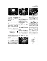
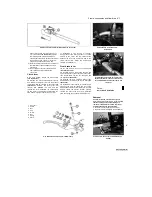
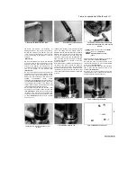
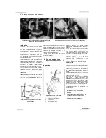
3.9b Unhook the springs and separate the
pushrod from the bracket (arrowed)
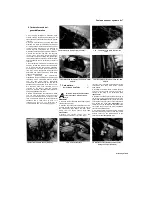
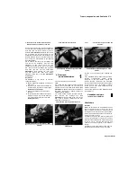
3.10 Unhook the springs at the back, then
remove the clevis pin (A) and unscrew the
pivot bolt (B)
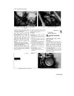
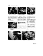
3.13 Sprocket cover bolts (arrowed)
Staned by Stalker

