6*22 Frame, suspension and final drive
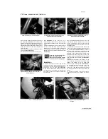
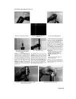
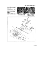
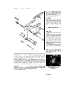
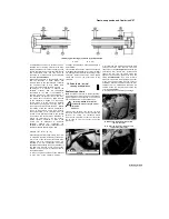
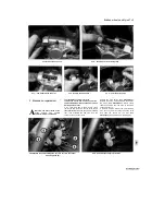
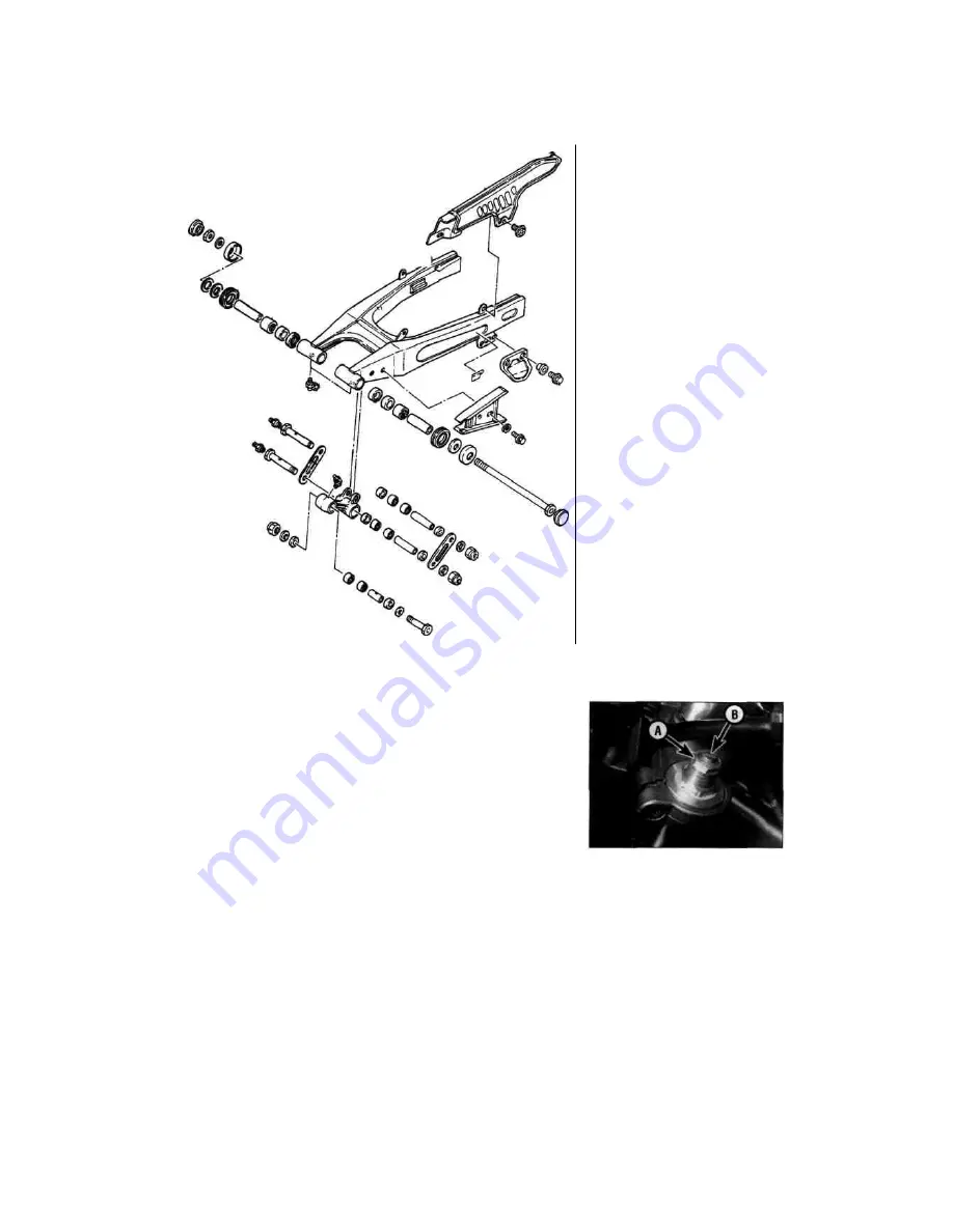
11.6b Suspension linkage and swingarm assembly
-
XTZ models
components, removing all traces of dirt, corrosion
and grease. On XTZ models make sure that the
grease nipple passages in the linkage arm and
pivot bolts are clear.
7 Inspect all components closely, looking for
obvious signs of wear such as heavy scoring, or
for damage such as cracks or distortion.
8 Check the condition of the needle roller
bearings in the linkage arm and swingarm.
9 Worn bearings can be drifted out of their bores,
but note that removal will destroy them; new
components should be obtained before work
commences. The new ones should be pressed or
drawn into their bores rather than driven into
position. In the absence of a press, a suitable
drawbolt arrangement can be made up as
described below.
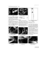
10 Obtain a long bolt or a length of threaded
rod from a local engineering works or some
other supplier. The bolt or rod should be
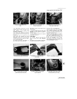
14 Lubricate the needle roller bearings and the
spacers with molybdenum disulphide grease
(TRX models) or lithium-based grease (XTZ
models) and install the inner sleeves.
15 Check the condition of the grease seals and
renew them if they are damaged or deteriorated.
Press the seals squarely into place.
Installation
16 Installation is the reverse of removal.
Apply molybdenum disulphide grease (TRX
models) or lithium-based grease (XTZ models)
to the pivot points. Install the bolts and nuts
finger-tight only until all components are in
position, then tighten the nuts to the torque
settings specified at the beginning of the
Chapter.
12 Suspension - adjustments %
Front forks
1 On XTZ models, the front forks are not
adjustable.
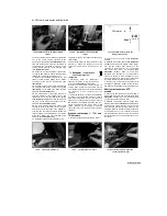
2 On TDM and TRX models, spring pre-load is
adjusted using a suitable spanner on the adjuster
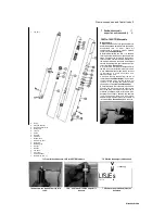
flats on the top of the forks (see illustration). The
amount of pre-load is indicated by lines on the
adjuster. There are five lines on TDM models and
eight on TRX models. The standard position is
with the fifth (1991 to 1995 TDM models), third
(1996-on TDM models) or sixth (TRX models)
line just visible above the top bolt hex. Turn the
adjuster clockwise to increase pre-load and anti-
clockwise to decrease it. Always make sure both
adjusters are set equally.
3 On TDM models, rebound damping is adjusted
using a screwdriver in the slot in the adjuster
protruding from the pre-load adjuster (see
illustration 12.2). The amount of damping is
indicated by the number of clicks when turned
anti-clockwise from the fully screwed-in position.
There are six positions on 1991 to 1995 TDM
models, and five on 1996-on TDM models. The
standard position is four clicks out. Turn the
adjuster clockwise
Scaned
by Stalker
about one inch longer than the combined width of
the linkage piece and one bearing. Also required are
suitable nuts and two large and robust washers
having a larger outside diameter than the bearing
housing. In the case of the threaded rod, fit one nut
to one end of the rod and stake it in place for
convenience.
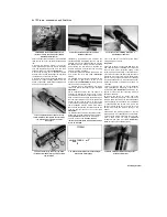
11 Fit one of the washers over the bolt or rod so
that it rests against the head or staked nut, then pass
the assembly through the relevant bore. Over the
projecting end place the bearing, which should be
greased to ease installation, followed by the
remaining washer and nut.
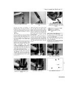
12 Holding the bearing to ensure that it is kept
square, slowly tighten the nut so that the bearing is
drawn into its bore.
13 Once it is fully home, remove the drawbolt
arrangement and, if necessary, repeat the procedure
to fit the other bearings.
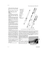
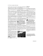
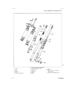
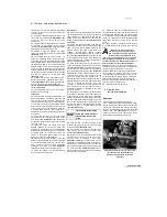
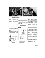
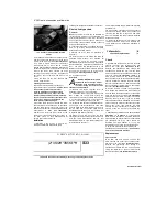
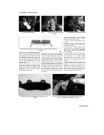
12.2 Spring pre-load adjuster (A), rebound
damping adjuster (B) - TDM and
TRX
models

