Electrical system 9*15
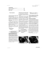
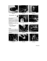
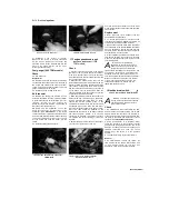
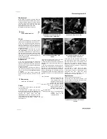
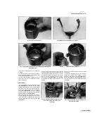
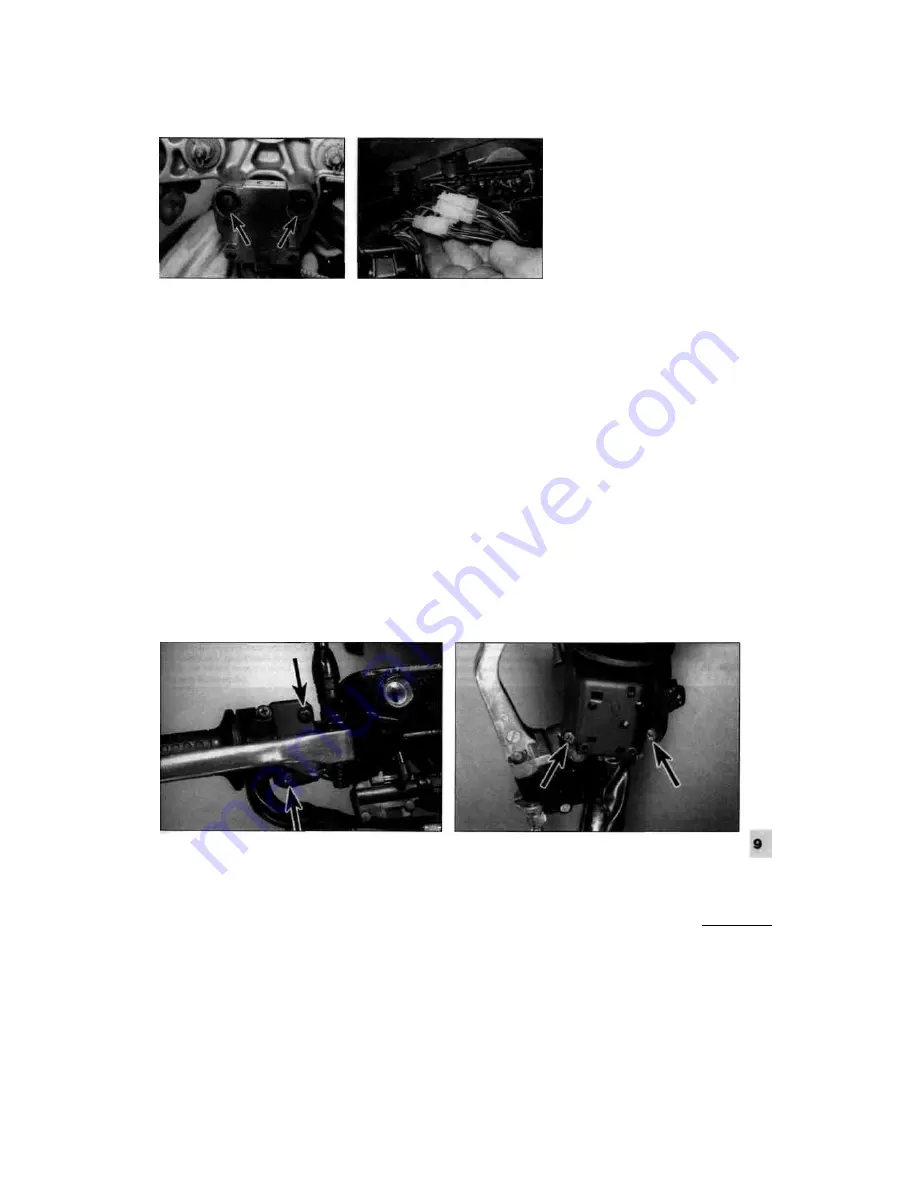
18.8 Ignition switch bolts (arrowed)
wiring back from the base of the switch and
disconnect it at the connector
(see
illustrations 18.1a and b and 15.3b).
Draw
the wiring through to the switch, freeing it
from any clips or ties and noting its routing.
5 On 1996-on TDM models, unscrew the
bolts securing the choke knob and the cable
guide to the top yoke. On TRX models,
unscrew the bolt securing the master cylinder
reservoir to the top yoke. On XTZ models,
unscrew the bolt securing the cable guide to
the top yoke.
6 Displace the handlebars from the top yoke
(see Chapter 6).
7 Slacken the fork clamp bolts in the top
yoke. Unscrew the steering stem nut or bolt
and remove it along with its washer, where
fitted. Lift the top yoke off the steering stem
and remove it.
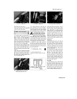
8 Two shear-head bolts mount the ignition
switch to the underside of the top yoke
(see
illustration).
The heads of the bolts must be
drilled off before the switch can be removed.
Mount the yoke in a vice equipped with soft
jaws and padded out with rags and drill off the
heads. Remove the bolts and withdraw the
switch from the top yoke.
Installation
9
Installation is the reverse of removal.
Tighten the new bolts until the heads shear
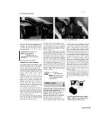
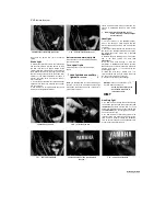
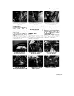
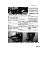
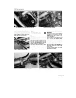
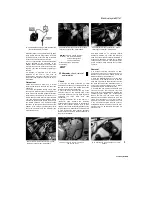
19.3 Handlebar switch wiring connectors -
TDM models
off. Make sure the wiring connector is
securely connected and correctly routed.
19 Handlebar switches
-
check
1
Generally speaking, the switches are
reliable and trouble-free. Most troubles,
when they do occur, are caused by dirty or
corroded contacts, but wear and breakage of
internal parts is a possibility that should not
be overlooked. If breakage does occur, the
entire switch and related wiring harness will
have to be renewed, as individual parts are not
available.
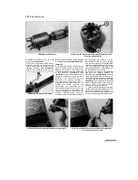
2 The switches can be checked for continuity
using an ohmmeter or a continuity test light.
Always disconnect the battery negative (-ve)
cable, which will prevent the possibility of a
short circuit, before making the checks.
3 On TDM models, remove the fairing (see
Chapter 8). On TRX models remove the air
filter housing, and on XTZ models remove the
fuel tank (see Chapter 4). Trace the wiring
harness of the switch in question back to its
connector and disconnect it
(see illustration
and 18.1b and 15.3b).
4
Check for continuity between the terminals
of the switch harness with the switch in the
various positions (ie switch off - no continuity,
switch on - continuity) - see the
wiring
diagrams
at the end of this Chapter. 5 If the
continuity check indicates a problem exists,
refer to Section 20, remove the switch and
spray the switch contacts with electrical
contact cleaner. If they are accessible, the
contacts can be scraped clean with a knife or
polished with crocus cloth. If switch
components are damaged or broken, it will be
obvious when the switch is disassembled.
20 Handlebar switches
-removal
and installation
Removal
1
If the switch is to be removed from the bike,
rather than just displaced from the handlebar,
trace the wiring harness of the switch in
question back to its connector(s) and
disconnect it/them. On TDM models, remove
the fairing (see Chapter 8). On TRX models
remove the air filter housing, and on XTZ
models remove the fuel tank (see Chapter 4).
Trace the wiring harness of the switch in
question back to its connector and
disconnect it
(see illustrations 19.3, 18.1b
and 15.3b).
Work back along the harness,
freeing it from all the relevant clips and ties,
whilst noting its correct routing.
2 On TDM and TRX models, disconnect the
wiring connectorfs) from the brake light switch
(if removing the right-hand switch) or the
clutch switch (if removing the left-hand switch)
(see illustrations 14.7a and b, or 23.2a).
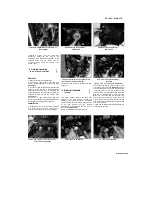
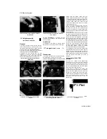
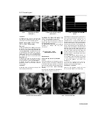
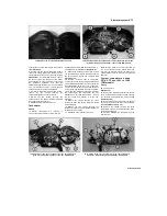
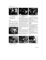
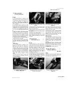
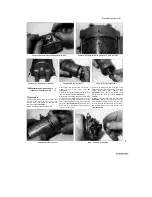
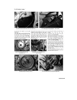
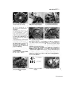
3
Unscrew the handlebar switch screws and
free the switch from the handlebar by
separating the halves
(see illustrations).
Installation
4
Installation is the reverse of removal. Make
sure the locating pin in the switch housing
locates in the hole in the handlebar and on
1999 TDM models ensure that the choke lever
locates correctly.
Staned by Stalker
1
20.3a Right-hand switch housing screws (arrowed) - TDM models 20.3b Left-hand switch housing screws (arrowed) - TDM models

