Electrical sysiefrFf^zf
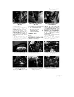
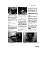
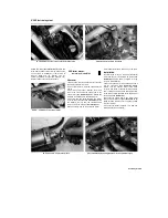
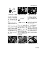
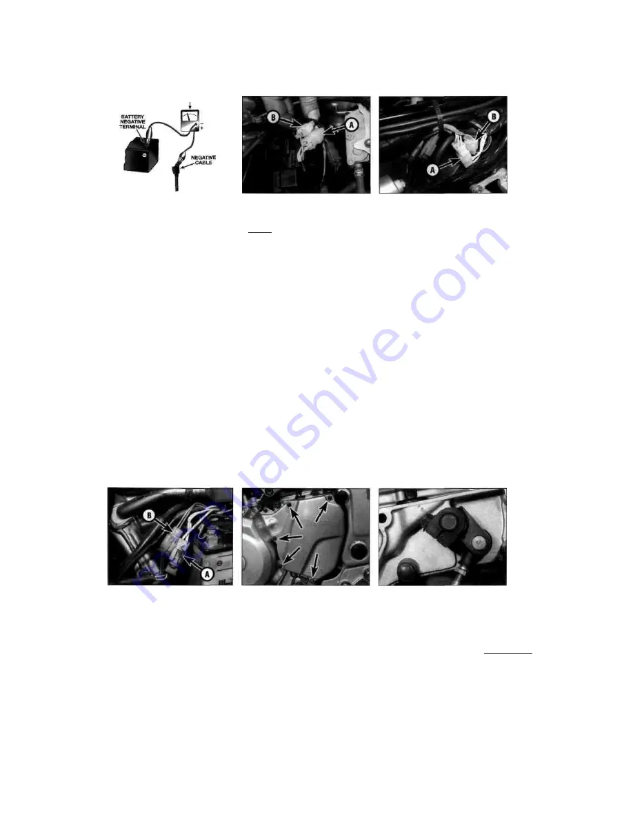
31.3 Checking the charging system leakage rate
- connect the ammeter as shown
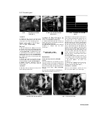
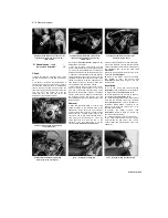
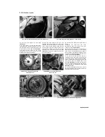
32.2a Alternator wiring connector (A), pickup
coil wiring connector (B) - TDM models
32.2b Alternator wiring connector (A), pickup
coil wiring connector (B) - TRX models
illustration). Always set the meter to a high amps
range initially and then bring it down to the mA
(milli Amps) range; if there is a high current flow
in the circuit it may blow the meter's fuse.
4 If the current leakage indicated exceeds the
amount specified at the beginning of the
Chapter, there is probably a short circuit in the
wiring. Disconnect the meter and connect the
negative (-ve) lead to the battery, tightening it
securely,
5 If leakage is indicated, use the wiring
diagrams at the end of this book to
systematically disconnect individual electrical
components and repeat the test until the source
is identified.
Output test
6 Start the engine and warm it up to normal
operating temperature. Remove the seat (see
Chapter 8).
7 To check the regulated voltage output, allow
the engine to idle and connect a multimeter set
to the 0 to 20 volts DC scale (voltmeter) between
the terminals of the battery (meter positive (+ve)
lead to battery positive terminal, meter negative
(-ve) lead to battery negative terminal). Slowly
increase the engine speed to 5000 rpm and note
the reading obtained. The regulated voltage
should be as specified at the beginning of the
Chapter. If the voltage is outside these limits,
check the alternator and the regulator (see
Sections 32 and 33).
HTOfB?!
Clues to a faulty regulator
"
™S™*™
are
constantly blowing
HINT
32 Alternator
- check, removal
and installation
Check
1 To access the wiring connectors, on TDM
models remove the seat, on TRX models remove
the side covers, and on XTZ models remove the
left-hand side cover (see Chapter 8).
2 Trace the wiring back from the top of the
alternator cover on the left-hand side of the
engine and disconnect it at the white connector
containing
the
three
white
wires
(see
illustrations).
3 Using a multimeter set to the ohms x 1
(ohmmeter) scale measure the resistance
between each of the white wires on the alternator
side of the connector, taking a total of three
readings, then check for continuity between each
terminal and earth. If the stator coil windings are
in good condition the three readings should be
within the range shown in the Specifications at
the start of this Chapter
and there should be no continuity (infinite
resistance) between any of the terminals and
earth. If not, the alternator stator coil assembly is
at fault and should be renewed. Note:
Before
condemning the stator coils, check the fault is not
due to damaged wiring between the connector
and coils.
Removal
4 To access the wiring connectors, on TDM
models remove the seat, on TRX models remove
the side covers, and on XTZ models remove the
left-hand side cover (see Chapter 8).
5 Trace the alternator/pick-up coil wiring back
from the top of the alternator cover on the left-
hand side of the engine and disconnect it at the
two white connectors (see illustrations 32.2a, b
and c). Free the wiring from any clips or guides
and feed it through to the alternator cover.
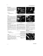
6 On TDM and XTZ models, unscrew the bolts
securing the outer front sprocket cover and
remove the cover (see illustration). Unscrew the
gearchange lever linkage arm pinchbolt and
remove the arm from the shaft, noting the
alignment of the punch mark with the slit in the
clamp (see illustration). If no mark is visible,
make your own before removing the arm so that
it can be correctly aligned with the shaft on
installation. Unscrew the bolts securing the inner
sprocket cover, on TDM models noting the clip
secured by the
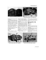
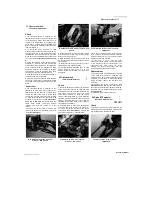
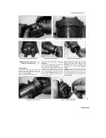
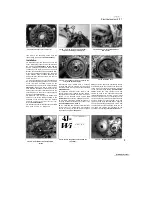
32.2c Alternator wiring connector (A), pickup
coil wiring connector (B) - XTZ models
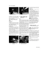
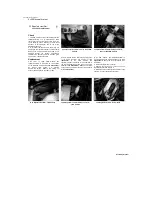
32.6a Unscrew the bolts (arrowed) and
remove the cover
32.6b Gearchange arm/shaft alignment -TDM
models
9
Scaned by
Stalker
bulbs, with brightness
varying considerably
with engine speed, and battery
overheating.
I

