Engine, clutch and transmission 2*13
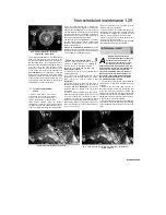
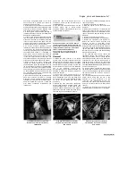
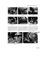
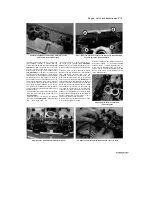
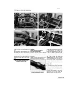
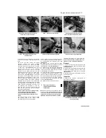
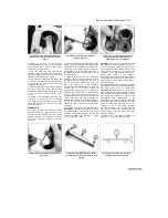
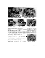
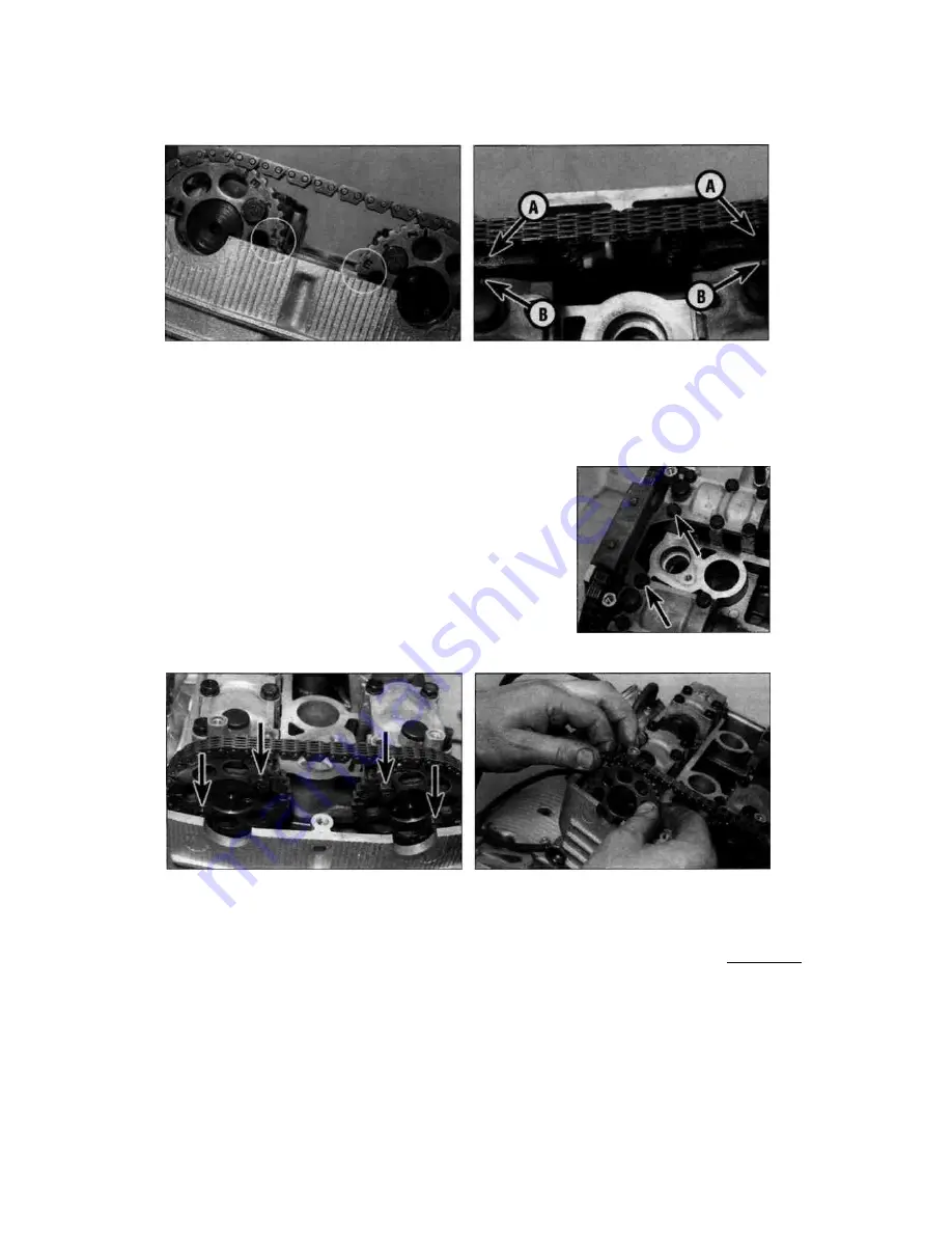
8.3b Note the alignment of the timing mark letters on the
sprockets with the cylinder head...
8.3c ... and of the punch marks (A) on the ends of the camshafts with
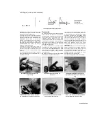
the lines (B) on the camshaft holders
surface and faces back, while the 'I' mark on the
inlet camshaft sprocket is parallel with the
cylinder head top surface and faces forward
(see
illustration).
Also the punch mark on each
camshaft sprocket holder faces up and aligns
with the mark on the top of the camshaft holder
(see illustration).
If you are in any doubt as to
the alignment of the markings, or if they are not
visible, make your own alignment marks between
all components, and also between a tooth on
each sprocket and its corresponding link on the
chain, before disturbing them. These markings
ensure that the valve timing can be correctly set
up on assembly without difficulty. As it is easy to
be a tooth out on installation, marking between a
tooth on each sprocket and its link in the chain is
especially useful.
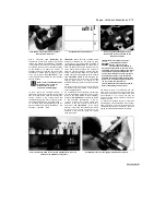
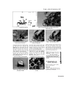
4 Unscrew the bolts securing the cam chain top
guide and remove the guide, noting how it fits
(see illustration).
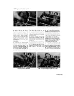
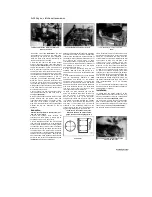
5 Slacken, but do not remove, the camshaft
sprocket bolts
(see illustration).
If the sprockets
turn, counter-hold them by
inserting a screwdriver or bar through the hole in
the centre of the camshaft
(see illustration
8.29a),
or by counter-holding the alternator rotor.
6 Remove the cam chain tensioner (see Section
9).
7 Make a mark on each sprocket to denote
whether it fits with the exhaust or inlet camshaft
(the
appropriate
existing
letter
can
be
highlighted). Remove the sprocket bolts, then
draw each sprocket off the end of its camshaft
and slip it out of the chain
(see illustration).
If
required, also lift the cam chain front guide out of
the front of the cam chain tunnel, noting how and
which way round it fits (see Section 24). While
the camshaft sprockets are off, don't allow the
cam chain to go slack and do not rotate the
crankshaft -the chain may drop down and bind
between the crankshaft and case, which could
damage these components. Wire the chain to
another component or secure it using a rod of
some sort to prevent it from dropping.
8 Before removing the camshaft holders, make
a note of which fits where. All the
holders are marked with a letter and number to
denote their location - I 1 is the inlet camshaft
holder on the No. 1 cylinder (left-hand) side, E 1
is the exhaust camshaft holder on the No. 1
cylinder, and so on. Also each holder is marked
with an arrow which points towards the cam
chain. Otherwise their
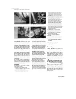
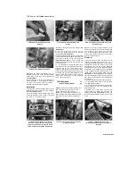
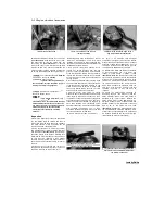
8.4 Unscrew the bolts (arrowed) and
remove the guide
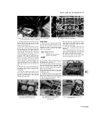
8.5 Slacken the camshaft sprocket bolts (arrowed)
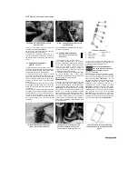
8.7 Slide the sprockets off the camshafts and out of the chain
Scaned by Stalker

