UNREGISTERED VERSION OF PICTURE-DESK
line, clutch and transmission 2*27
1
{?
A
t)
B
)
1
kl
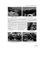
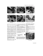
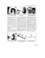
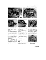
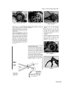
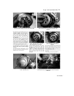
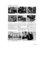
14.13a Slip the pin (A) into the piston (B)
and try to rock it back and forth. If it's
loose, renew the piston and pin
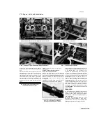
14.13b Measuring the internal diameter of
the bore in the piston
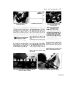
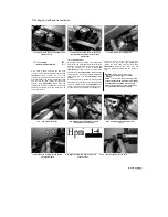
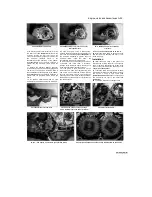
14.16a Align the piston with the
connecting rod small-end and insert the
pin
13
Apply clean engine oil to the piston pin,
insert it into the piston and check for any
freeplay between the two
(see illustration).
Measure the pin external diameter
(see
illustration 28.6b),
and the pin bore in the
piston
(see
illustration).
Calculate
the
difference to obtain the piston pin-to-piston
pin bore clearance. Compare the result to the
specifications at the beginning of the Chapter.
If the clearance is greater than specified,
renew the components that are worn beyond
their specified limits.
Installation
14 Inspect and install the piston rings (see
Section 15).
15 Lubricate the piston pin, the piston pin bore
and the connecting rod small-end bore with clean
engine oil.
16 When installing the pistons onto the
connecting rods, make sure that the arrow points
towards the exhaust side of the engine
(see
illustration 14.2).
If both circlips were removed,
install a new circlip in one side of the piston (do
not re-use old circlips). Line up the piston on its
correct connecting rod, and insert the piston pin
from the other side
(see illustration).
Secure the
pin with the other new circlip. When installing the
circlips, compress them only just enough to fit
them in the piston, and make sure they are
properly seated in their grooves with the open
end
away from the removal notch
(see
illustration).
17
Install the cylinder block (see Section 13).
15 Piston rings
-
inspection and installation
1
It is good practice to renew the piston rings
when an engine is being overhauled. Before
installing the new piston rings, the ring end gaps
must be checked with the rings installed in the
cylinder.
2 Lay out each piston with its new ring sets so
the rings will be matched with the same piston
and cylinder during the end gap measurement
procedure and engine assembly.
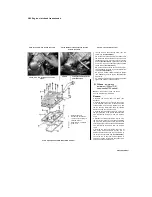
3 To measure the installed ring end gap, insert
the top ring into the top of the first cylinder and
square it up with the cylinder walls by pushing it
in with the top of the piston. The ring should be
about 20 mm below the top edge of the cylinder.
To measure the end gap, slip a feeler gauge
between the ends of the ring and compare the
measurement to the specifications at the
beginning of the Chapter
(see illustration).
4
If the gap is larger or smaller than specified,
double check to make sure that you have the
correct rings before proceeding.
5
If the gap is too small, it must be enlarged or
the ring ends may come in contact with each
other during engine operation, which can cause
serious damage. The end gap can be increased
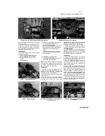
by filing the ring ends very carefully with a fine
file. When performing this operation, file only
from the outside in
(see illustration).
6
Excess end gap is not critical unless it
exceeds the service limit. Again, double-check to
make sure you have the correct rings for your
engine and check that the bore is not worn.
7 Repeat the procedure for each ring that will be
installed in the cylinders. When checking the oil
ring, only the side-rails can be checked as the
ends of the expander ring should contact each
other. Remember to keep the rings, pistons and
cylinders matched up.
8 Once the ring end gaps have been
checked/corrected, the rings can be installed on
the pistons.
9 The oil control ring (lowest on the piston) is
installed first. It is composed of three separate
components, namely the expander and the upper
and lower side rails. Slip the expander into the
groove, then install the upper side rail.
Do not use a piston ring installation tool on the 2 oil
ring side rails as they may be damaged. Instead, place
one end of the side rail into the groove between the
expander and the ring land. Hold it firmly in place and
slide a finger
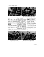
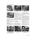
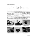
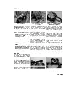
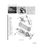
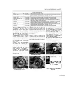
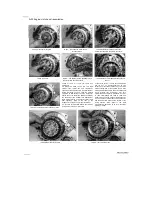
14.16b Do not over-compress the circlip
when fitting it into the piston
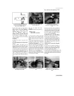
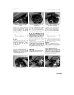
15.3 Measuring piston ring installed end
gap
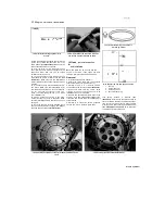
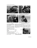
15.5 Ring end gap can be enlarged by
clamping a file in a vice and filing the ring
ends
Staned by Stalker
UNREGISTERED VERSION OF PICTURE-DESK

