UNREGISTERED VERSION OF PICTURE-DESK
line, clutch and transmission 2»35
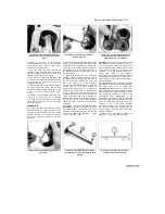
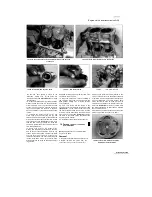
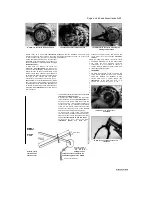
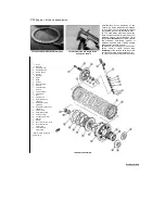
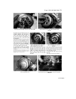
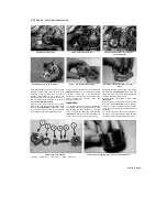
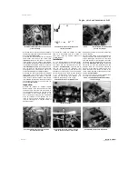
17.5 Bend the tab to secure the cable in
the lever
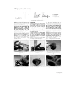
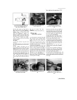
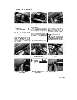
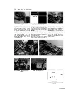
18.2 The gear should rotate freely in the
direction shown
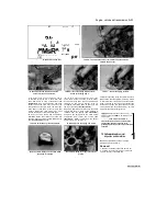
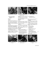
18.4 Check the surface of the hub (A) and
the sprags (B) as described
5
Installation is the reverse of removal. Apply
grease to the cable ends. Make sure the cable is
correctly routed. Secure the cable end in the
operating lever by bending the tab against it
(see
illustration).
Adjust the amount of clutch lever
freeplay (see Chapter 1).
18 Starter clutch and
!fe>
idle/reduction gear - removal, £&
inspection and installation
3^
Removal
1 Remove the alternator rotor (see Chapter
9). The starter driven gear should come away
with the rotor. If it doesn't, remove it from the
crankshaft. The starter clutch is secured to
the back of the rotor by three Allen bolts on
the inside of the rotor.
Inspection
2 Install the starter driven gear into the starter
clutch (if removed) and, with the rotor face down
on a workbench, check that the gear rotates
freely in an anti-clockwise direction and locks
against the rotor in a clockwise direction
(see
illustration).
If it doesn't, renew the starter clutch
- no replacement parts are available.
3 Withdraw the starter driven gear from the
starter clutch
(see illustration 18.4).
If it appears
stuck, rotate it anti-clockwise as you withdraw it
to free it from the starter clutch. Note the thrust
washer fitted inside the starter clutch and remove
it for safekeeping
(see illustration 18.7).
4
Check the bearing surface of the starter driven
gear hub and the condition of the sprags inside
the clutch body
(see illustration).
If the bearing
surface shows signs of excessive wear or the
sprags are damaged, marked or flattened at any
point, the starter clutch should be renewed.
5 Examine the teeth of the starter idle/reduction
gear and the corresponding teeth of the starter
driven gear and starter motor shaft. Renew the
gears and/or starter motor if worn or chipped
teeth are discovered.
6 To renew the starter clutch sprag assembly,
hold the alternator rotor in a rotor holder then
undo the three bolts securing the clutch to the
rotor. Remove the clutch from the back of the
rotor and install the new one back onto the rotor.
Tighten the bolts to the torque setting specified at
the beginning of the Chapter, using the rotor
holder to hold the rotor. Lubricate the starter
clutch sprags with new engine oil.
Installation
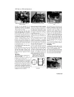
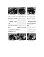
7 Install the thrust washer in the starter clutch
(see illustration).
Lubricate the hub of the
starter driven gear with clean engine oil, then
install it into the clutch, rotating it clockwise
as you do so to spread the rollers and allow
the hub of the gear to enter
(see illustration
18.4).
8
Install the alternator rotor (see Chapter 9).
19 Gearchange mechanism
§|
external components - removal, s£
inspection and installation
^
Note:
The gearchange mechanism (external
components) can be removed with the engine in
the frame. If the engine has been removed,
ignore the steps which don't apply.
Removal
1
Make sure the transmission is in neutral.
2 Remove the alternator cover (see Chapter 9).
If required, disconnect the alternator and pick-up
coil wiring connectors, otherwise ignore those
Steps and lay the cover down so as not to strain
the wiring.
3 Remove the clutch (see Section 16).
4 Remove the E-clip securing the left-hand end
of the gearchange shaft in the crankcase, and
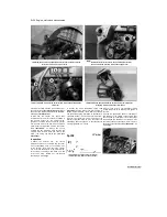
slide the washer off the shaft
(see illustrations).
5 Note how the gearchange shaft centralising
spring ends fit on each side of the locating pin in
the casing, and how the pawls on the
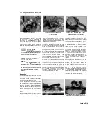
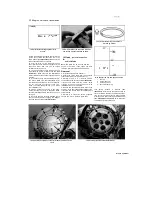
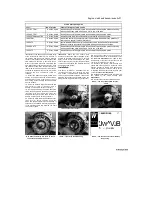
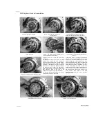
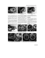
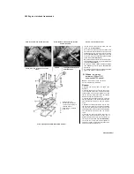
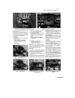
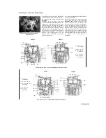
18.7 Do not omit the thrust washer
19.4a Remove the E-clip
...
19.4b ... and slide off the washer
Staned by Stalker

