Engine, clutch and transmission 2«39
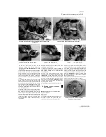
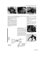
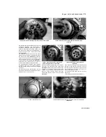
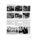
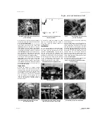
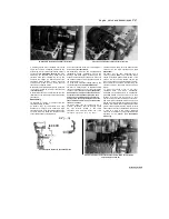
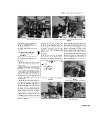
20.10a Assembled oil pump
in the slots in the rotor, then fit the inner rotor into
the outer rotor
(see illustration).
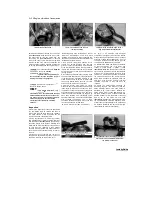
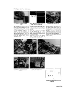
Measure the
clearance between the inner rotor tip and the
outer rotor with a feeler gauge and compare it to
the
maximum
clearance
listed
in
the
specifications at the beginning of the Chapter
(see illustration).
If the clearance measured is
greater than the maximum listed, renew the
pump.
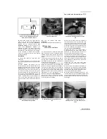
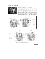
11 Measure the clearance between the outer
rotor and the pump body with a feeler gauge and
compare it to the maximum clearance listed in
the specifications at the beginning of the Chapter
(see illustration).
If the clearance measured is
greater than the maximum listed, renew the
pump.
12 On 1996-on TDM models and all TRX
models, lay a straight-edge across the rotors and
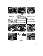
20.10b Measuring inner rotor tip-to-outer
rotor tip clearance
the pump body and, using a feeler gauge,
measure the rotor end-float (the gap between the
rotors and the straight-edge
(see illustration).
If
the clearance measured is greater than the
maximum
listed,
renew
the
pump.
No
specifications are given for other models.
13 Check the nylon pump driven gears for wear
or damage, and renew them if necessary.
Damage to the steel drive gear is unlikely, but if
found will necessitate crankshaft renewal.
14 If the pump is good, make sure all the
components are clean, then lubricate them with
new engine oil. Assemble the housing, making
sure the pins locate correctly, and tighten the
assembly screw to the torque setting specified at
the beginning of the Chapter, not forgetting the
cam chain guide on
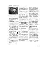
20.11 Measuring outer rotor-to-body
clearance
the feed pump
(see illustration 20.7b and a).
15
Rotate the pump shaft by hand and check
that the rotors turn smoothly and freely. If not,
renew the pump.
Installation
16
Install the pump using a new gasket, not
forgetting the locating dowel for the scavenge
pump, if removed, and tighten the screws to the
torque setting specified at the beginning of the
Chapter
(see illustrations).
17
Locate the pump driven gear onto its shaft,
aligning the flat in the gear with that on the shaft,
and secure it using a new circlip
(see
illustrations 20.5b and a).
Align the open end of
the circlip with the flat on the shaft
(see
illustration).
18
If removed, install the oil passage collar
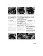
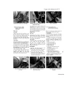
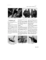
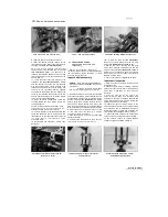
20.12 Measuring rotor end-float
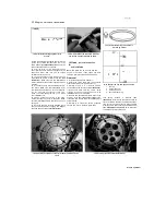
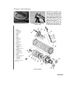
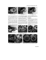
20.16a Fit the gasket, on the scavenge
pump locating it onto the dowel (arrowed)
20.16b Install the pump ...
20.16c ... and tighten its screws to the specified torque
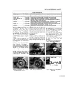
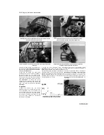
20.17 Align the open ends of the circlips with the flats on the shafts
Started by Stalker

