2»48 Engine, clutch and transmission
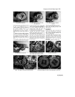
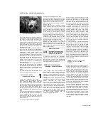
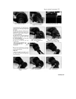
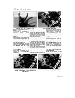
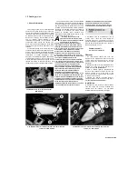
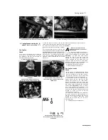
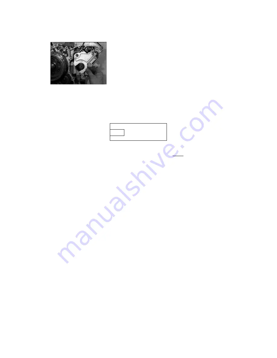
25.20 Install the retainer plate
18 Turn the engine over. Clean the threads of
the 8 and 6 mm upper crankcase bolts and apply
new engine oil to their threads. Insert them (with
their washers where fitted) in their original
locations. Secure all bolts finger-tight at first, then
tighten them evenly and a little at a time in the
correct numerical sequence to the torque settings
specified at the beginning of the Chapter (see
illustrations 25.4a or b).
19 With all crankcase fasteners tightened,
check that the crankshaft and transmission
shafts rotate smoothly and easily. Check that the
transmission
shafts
rotate
freely
and
independently in neutral, then rotate the selector
drum by hand and select each gear in turn whilst
rotating the input shaft. Check that all gears can
be selected and that the shafts rotate freely in
every gear. If there are any signs of undue
stiffness, tight or rough spots, or of any other
problem, the fault must be rectified before
proceeding further.
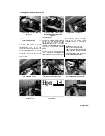
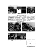
20 Install the transmission output shaft retainer
plate onto the left-hand side of the crankcase
(see illustration). Apply a suitable non-permanent
thread locking compound to the threads of the
bolts and tighten them to the specified torque
setting.
21 Install all other removed assemblies in the
reverse of the sequence given in Step 2.
26 Crankcase halves -
inspection and servicing
1 After the crankcases have been
separated, remove the crankshaft, connecting
rods, transmission shafts, selector drum and
forks, water pump drive gear, and neutral switch,
referring to the relevant Sections of this Chapter,
and to Chapter 3 for the water pump and Chapter
9 for the neutral switch. Also remove the oil
passage collars and their O-rings (see illustration
22.9). Discard the O-rings as new ones must be
used.
2 The crankcases should be cleaned thoroughly
with new solvent and dried with compressed air.
All oil passages should be blown out with
compressed air. Also check that the oil nozzles
are securely screwed into their bores and have
not worked loose.
3 All traces of old gasket sealant should be
removed from the mating surfaces. Minor
damage to the surfaces can be cleaned up with a
fine sharpening stone or grindstone.
Caution: Be
very careful not to nick or gouge the crankcase
mating surfaces or oil leaks will result. Check
both crankcase halves very carefully for cracks
and other damage.
4 Small cracks or holes in aluminium castings
may be repaired with an epoxy resin adhesive as
a temporary measure. Permanent repairs can
only be effected by argon-arc welding, and only a
specialist in this process is in a position to advise
on the economy or practical aspect of such a
repair. If any damage is found that can't be
repaired, renew the crankcase halves as a set.
5 Damaged threads can be economically
reclaimed by using a diamond section wire insert,
of the Heli-Coil type, which is easily fitted after
drilling and re-tapping the affected thread.
6 Sheared studs or screws can usually be
removed with screw extractors, which consist of
a tapered, left thread screw of very hard steel.
These are inserted into a pre-drilled hole in the
stud, and usually succeed in dislodging the most
stubborn stud or screw.
Refer to Tools and
HINT
Workshop Tips for details of
installing a thread insert and
using screw extractors.
7 Install all components and assemblies,
referring to the relevant Sections of this Chapter
and to Chapters 3 and 9, before reassembling
the crankcase halves. Do not forget to install the
oil passage collars using new O-rings.
27 Main and connecting rod
bearings
- general information
1 Even though main and connecting rod
bearings are generally renewed during the
engine overhaul, the old bearings should be
retained for close examination as they may
reveal valuable information about the condition of
the engine.
2 Bearing failure occurs mainly because of lack
of lubrication, the presence of dirt or other foreign
particles,
overloading
the
engine
and/or
corrosion. Regardless of the cause of bearing
failure, it must be corrected before the engine is
reassembled to prevent it from happening again.
3 When examining the connecting rod bearings,
remove them from the connecting rods and caps
and lay them out on a clean surface in the same
general position as their location on the
crankshaft journals. This will enable you to match
any
noted
bearing
problems
with
the
corresponding crankshaft journal.
4 Dirt and other foreign particles get into the
engine in a variety of ways. It may be left in the
engine during assembly or it may pass through
filters or breathers. It may get into the oil and
from there into the bearings. Metal chips from
machining operations and normal engine wear
are often present. Abrasives are sometimes left
in engine components after reconditioning
operations, especially when parts are not
thoroughly cleaned using the proper cleaning
methods. Whatever the source, these foreign
objects often end up imbedded in the soft bearing
material and are easily recognised. Large
particles will not imbed in the bearing and will
score or gouge the bearing and journal. The best
prevention for this cause of bearing failure is to
clean all parts thoroughly and keep everything
spotlessly clean during engine reassembly.
Frequent and regular oil and filter changes are
also recommended.
5 Lack of lubrication or lubrication breakdown
has a number of interrelated causes. Excessive
heat (which thins the oil), overloading (which
squeezes the oil from the bearing face) and oil
leakage or throw off (from excessive bearing
clearances, worn oil pumps or high engine
speeds) all contribute to lubrication breakdown.
Blocked oil passages will also starve a bearing
and destroy it. When lack of lubrication is the
cause of bearing failure, the bearing material is
wiped or extruded from the steel backing of the
bearing. Temperatures may increase to the point
where the steel backing and the journal turn blue
from overheating.
[*CT?B3I
Refer to Tools and
TJJJJJT
Workshop Tips for bearing
HlMT
faultfinding.
6 Riding habits can have a definite effect on
bearing life. Full throttle low speed operation, or
labouring the engine, puts very high loads on
bearings, which tend to squeeze out the oil film.
These loads cause the bearings to flex, which
produces fine cracks in the bearing face (fatigue
failure). Eventually the bearing material will
loosen in pieces and tear away from the steel
backing. Short trip riding leads to corrosion of
bearings, as insufficient engine heat is produced
to drive off the condensed water and corrosive
gases produced. These products collect in the
engine oil, forming acid and sludge. As the oil is
carried to the engine bearings, the acid attacks
and corrodes the bearing material.
7 Incorrect bearing installation during engine
assembly will lead to bearing failure as well. Tight
fitting bearings which leave insufficient bearing oil
clearances result in oil starvation. Dirt or foreign
particles trapped behind a bearing insert result in
high spots on the bearing which lead to failure.
8 To avoid bearing problems, clean all parts
thoroughly before reassembly, double check all
bearing clearance measurements and lubricate
the new bearings with clean engine oil during
installation.
Scaned by Stalker
1

