FEATURES
1-6
To set the clock:
1. Push the “SELECT” switch to change the dis-
play to the clock mode.
2. Push the “SELECT” and “RESET” switches
together for at least two seconds.
3. When the hour digits start flashing, push the
“RESET” switch to set the hours.
4. Push the “SELECT” switch, and the minute
digits will start flashing.
5. Push the “RESET” switch to set the minutes.
6. Push the “SELECT” switch and then release
it to start the clock.
Self-diagnosis device
This model is equipped with a self-diagnosis de-
vice for various electrical circuits.
If any of those circuits are defective, the engine
trouble warning light will come on, and then the
odometer/tripmeter/clock display will indicate a
two-digit error code (e.g., 12, 13, 14).
If the odometer/tripmeter/clock display indicates
any error codes, note the code number, and
then check the vehicle. Refer to “FUEL INJEC-
TION SYSTEM” on page 7-27.
CAUTION:
EC1D71018
If the display indicates an error code, the ve-
hicle should be checked as soon as possible
in order to avoid engine damage.
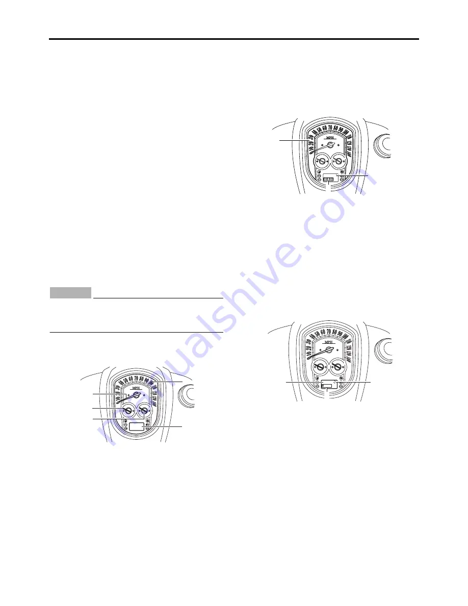
Brightness control mode
The brightness can be adjusted for the following:
• the multi-function meter unit panel (item num-
ber “1”)
• the LCD (item number “2”)
• the speedometer, tachometer, and the fuel
gauge needles (item number “3”)
Select the brightness control mode as follows.
1. Turn the key to “OFF”.
2. Push and hold the “SELECT” switch.
3. Turn the key to “ON”, and then release the
“SELECT” switch after five seconds.
Item number “1” is displayed.
4. Adjust the multi-function meter unit panel
brightness level by pushing the “RESET”
switch.
5. Push the “SELECT” switch to select the LCD.
Item number “2” is displayed.
Adjust the LCD brightness level by pushing
the “RESET” switch.
6. Push the “SELECT” switch to select the
speedometer, tachometer, and the fuel
gauge needles.
Item number “3” is displayed.
Adjust the brightness level of the speedome-
ter, tachometer, and the fuel gauge needles
by pushing the “RESET” switch.
1. Multi-function meter unit panel
2. LCD
3. Speedometer needle
4. Tachometer needle
5. Fuel gauge needle
2
3
4
5
1
1. Multi-function meter unit panel
2. Item number
3. Brightness level
1. LCD
2. Item number
3. Brightness level
2
3
1
2
3
1
Summary of Contents for XV19SW 2006
Page 6: ......
Page 8: ......
Page 24: ...SPECIAL TOOLS 1 15...
Page 55: ...LUBRICATION POINTS AND LUBRICANT TYPES 2 30...
Page 60: ...LUBRICATION SYSTEM CHART AND DIAGRAMS 2 35 D D B B D D C C A A B C C B 3 2 1 3 4 6 7 6 7 5...
Page 62: ...LUBRICATION SYSTEM CHART AND DIAGRAMS 2 37 A A A A 1 3 2 4...
Page 64: ...LUBRICATION SYSTEM CHART AND DIAGRAMS 2 39 A 1 2 3 4...
Page 66: ...LUBRICATION SYSTEM CHART AND DIAGRAMS 2 41 A A A 1 5 5 1 3 2 4 B B B B...
Page 68: ...LUBRICATION SYSTEM CHART AND DIAGRAMS 2 43 1 2...
Page 69: ...LUBRICATION SYSTEM CHART AND DIAGRAMS 2 44 1 Transfer gear oil pump 2 Middle driven shaft...
Page 78: ...CABLE ROUTING 2 53...
Page 86: ...CABLE ROUTING 2 61...
Page 89: ......
Page 122: ...ELECTRICAL SYSTEM 3 33 a b 1...
Page 125: ......


