4-22
VALVES AND VALVE SPRINGS
ENG
*****************************************************
*****************************************************
NOTE:
a
b
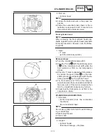
VALVE AND VALVE SPRING REMOVAL
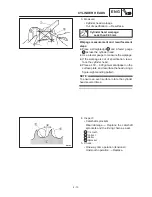
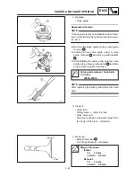
1. Check:
S
Valve sealing
Leakage at the valve seat
Inspect the
valve face, valve seat and valve seat
width.
Refer to “INSPECTION”.
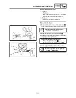
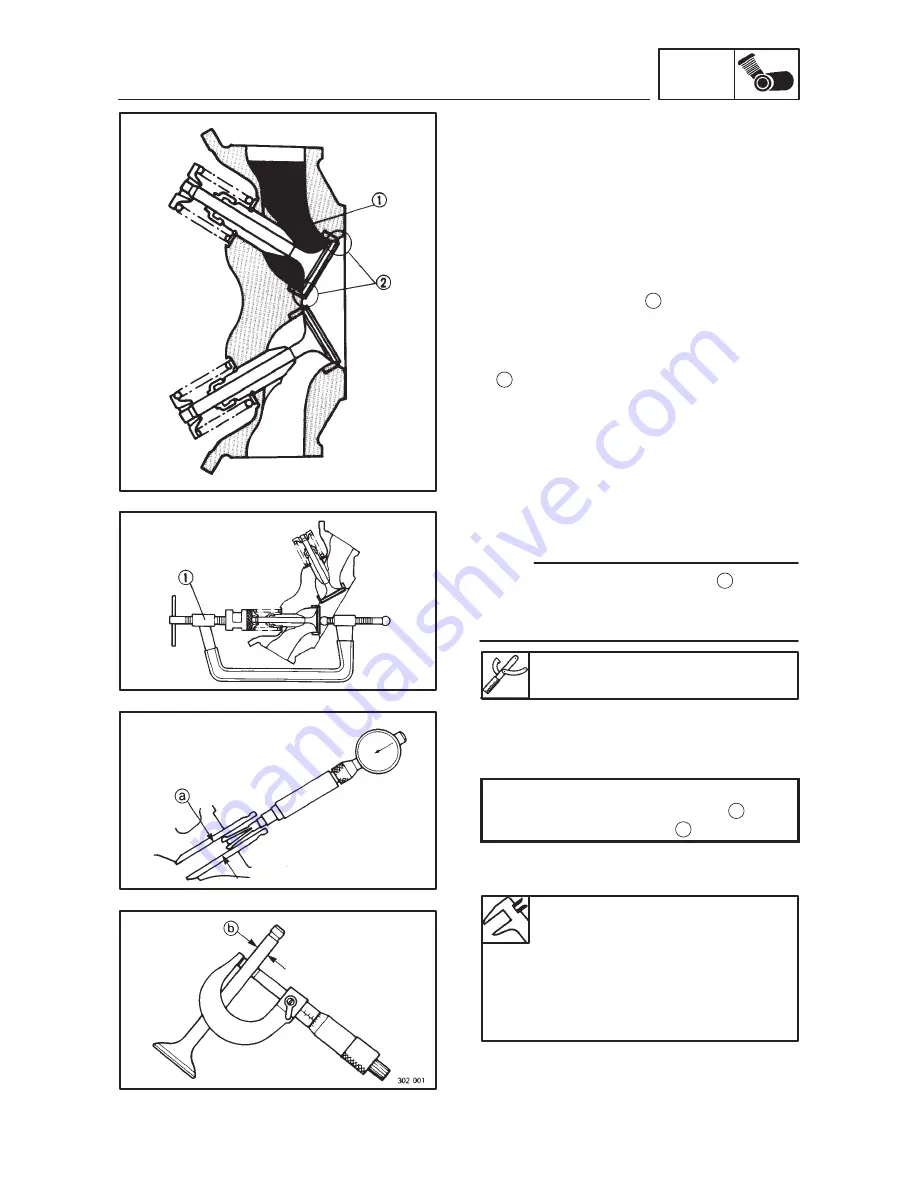
Checking steps:
D
Pour a clean solvent
1
into the intake and
exhaust ports.
D
Check that the valve seals properly.
There should be no leakage at the valve seat
2
.
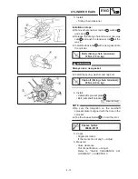
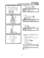
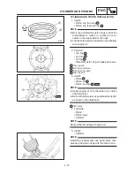
2. Remove:
S
Valve cotters
Attach a valve spring compressor
1
between
the valve spring retainer and the cylinder head
to remove the valve cotters.
Valve spring compressor:
90890-04019
VALVE AND VALVE SPRING INSPECTION
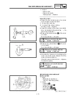
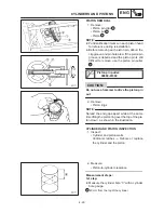
1. Measure:
S
Stem-to-guide clearance
Stem-to-guide clearance =
valve guide inside diameter –
valve stem diameter
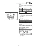
Out of specification
Replace the valve
guide.
Clearance (stem to guide):
Intake:
0.010
0.037 mm
<Limit>:
0.08 mm
Exhaust:
0.025
0.052 mm
<Limit>:
0.10 mm
Summary of Contents for XVS6501997
Page 1: ......
Page 2: ......
Page 8: ......
Page 10: ...GEN INFO ...
Page 18: ...GEN INFO ...
Page 20: ...SPEC ...
Page 44: ...2 24 LUBRICATION DIAGRAMS SPEC 1 Crankshaft 2 Oil filter 3 Oil pump ...
Page 102: ...INSP ADJ ...
Page 188: ...CARB ...
Page 198: ...CARB ...
Page 266: ...CHAS ...
Page 268: ...ELEC SELF DIAGNOSIS 7 49 TROUBLESHOOTING 7 50 ...
Page 298: ...E 7 30 SIGNAL SYSTEM ELEC EB806000 SIGNAL SYSTEM CIRCUIT DIAGRAM ...
Page 320: ...TRBL SHTG ...
Page 326: ...TRBL SHTG ...

