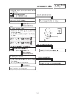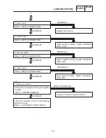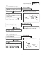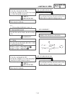
7-27
LIGHTING SYSTEM
ELEC
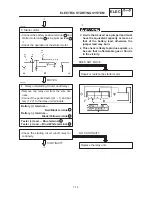
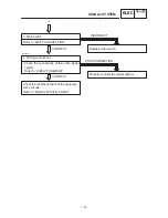
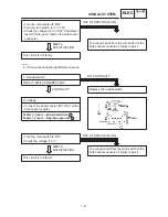
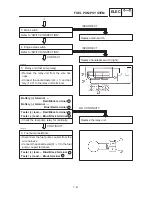
1. Bulb and bulb socket
S
Check the bulb and bulb socket for continu-
ity.
Replace the bulb and / or bulb socket.
NO CONTINUITY
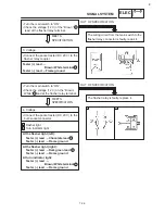
2. Voltage
S
Connect the pocket tester (DC 20 V) to the
headlight and high beam indicator light cou-
plers.
When the dimmer switch is on “LO”.
When the dimmer switch is on “HI”.
CONTINUITY
A
B
Headlight:
Tester (+) lead
Yellow terminal or Green terminal
Tester (–) lead
Black terminal
High beam indicator light:
Tester (+) lead
Yellow terminal
Tester (–) lead
Black terminal
S
Turn the main switch to “ON”.
S
Turn the dimmer switch to “LO” or “HI”.
S
Check the voltage (12 V) of the “Green” and
“Yellow” leads on the bulb socket connec-
tor.
The wiring circuit from the main switch to the
bulb socket connector is faulty, repair it.
OUT OF SPECIFICATION
This circuit is not faulty.
B
Headlight connector
4
1
3
2
5
Meter connector
MEETS
SPECIFICATION
EB805020
LIGHTING SYSTEM CHECK
1. If the headlight and the high beam indicator
light fail to come on:
Summary of Contents for XVS6501997
Page 1: ......
Page 2: ......
Page 8: ......
Page 10: ...GEN INFO ...
Page 18: ...GEN INFO ...
Page 20: ...SPEC ...
Page 44: ...2 24 LUBRICATION DIAGRAMS SPEC 1 Crankshaft 2 Oil filter 3 Oil pump ...
Page 102: ...INSP ADJ ...
Page 188: ...CARB ...
Page 198: ...CARB ...
Page 266: ...CHAS ...
Page 268: ...ELEC SELF DIAGNOSIS 7 49 TROUBLESHOOTING 7 50 ...
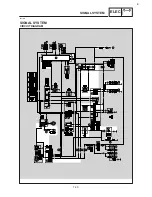
Page 298: ...E 7 30 SIGNAL SYSTEM ELEC EB806000 SIGNAL SYSTEM CIRCUIT DIAGRAM ...
Page 320: ...TRBL SHTG ...
Page 326: ...TRBL SHTG ...


