7-41
S
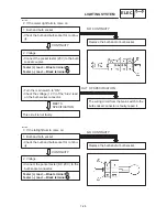
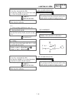
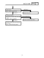
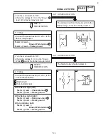
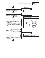
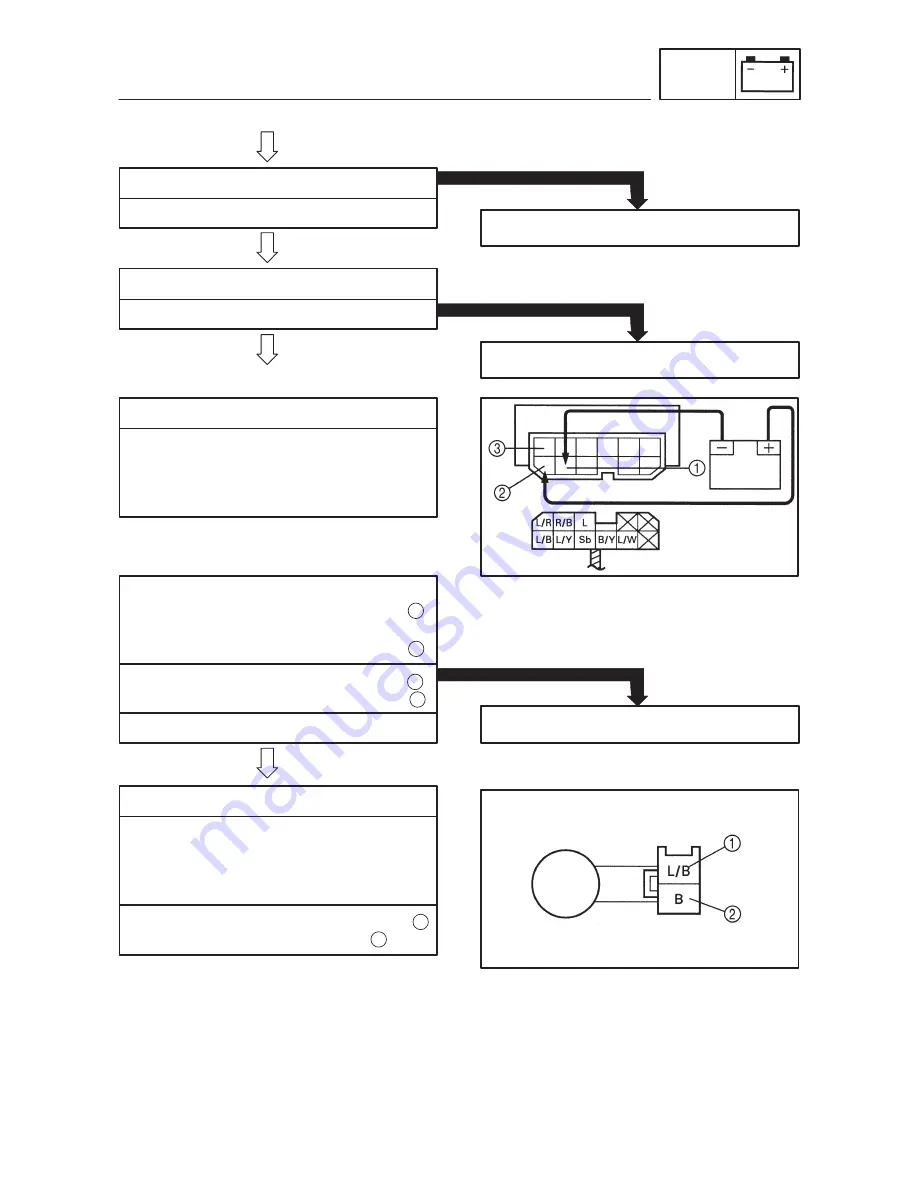
Remove the relay unit from the wire har-
ness.
S
Connect the pocket tester (
Ω
1) and bat-
tery (12 V) to the relay unit terminals.
3. Main switch
Refer to “SWITCH INSPECTION”.
Replace main switch.
INCORRECT
:
4. Engine stop switch
Refer to “SWITCH INSPECTION”.
Replace handlebar switch (right).
INCORRECT
EB803023
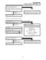
5. Relay unit (fuel pump relay)
Battery (+) terminal
Red / Black terminal
Battery (–) terminal
Blue / Red terminal
1
2
S
Check the fuel pump relay for continuity.
Tester (+) lead
Red / Black terminal
Tester (–) lead
Blue / Black terminal
3
Replace the relay unit.
NO CONTINUITY
CONTINUITY
EB808021
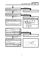
6. Fuel pump resistance
S
Disconnect the fuel pump coupler from the
wire harness.
S
Connect the pocket tester (
Ω
1) to the fuel
pump coupler terminals.
Tester (+) lead
Blue / Black terminal
Tester (–) lead
Black terminal
1
2
CORRECT
1
FUEL PUMP SYSTEM
ELEC
Summary of Contents for XVS6501997
Page 1: ......
Page 2: ......
Page 8: ......
Page 10: ...GEN INFO ...
Page 18: ...GEN INFO ...
Page 20: ...SPEC ...
Page 44: ...2 24 LUBRICATION DIAGRAMS SPEC 1 Crankshaft 2 Oil filter 3 Oil pump ...
Page 102: ...INSP ADJ ...
Page 188: ...CARB ...
Page 198: ...CARB ...
Page 266: ...CHAS ...
Page 268: ...ELEC SELF DIAGNOSIS 7 49 TROUBLESHOOTING 7 50 ...
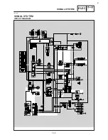
Page 298: ...E 7 30 SIGNAL SYSTEM ELEC EB806000 SIGNAL SYSTEM CIRCUIT DIAGRAM ...
Page 320: ...TRBL SHTG ...
Page 326: ...TRBL SHTG ...


