2-32
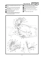
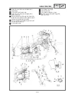
h To the flasher light relay.
i To the rear fender.
To the battery negative (–) lead.
k Pass the ignitor unit leads through the
battery box hole.
j
b Fasten the wire harness and leads with a
metal clamp.
c To the carburetor heater relay.
d Fasten the wire harness and leads with a
plastic locking tie.
e Pass the plastic band through the frame hole.
Fasten the wire harness with a plastic band at
the point where the tape is located.
f The wire harness and leads should not touch
the rear shock absorber.
g To the starter relay.
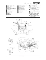
CABLE ROUTING
SPEC
Summary of Contents for XVS6501997
Page 1: ......
Page 2: ......
Page 8: ......
Page 10: ...GEN INFO ...
Page 18: ...GEN INFO ...
Page 20: ...SPEC ...
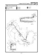
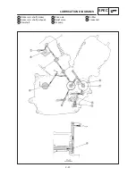
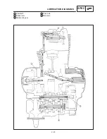
Page 44: ...2 24 LUBRICATION DIAGRAMS SPEC 1 Crankshaft 2 Oil filter 3 Oil pump ...
Page 102: ...INSP ADJ ...
Page 188: ...CARB ...
Page 198: ...CARB ...
Page 266: ...CHAS ...
Page 268: ...ELEC SELF DIAGNOSIS 7 49 TROUBLESHOOTING 7 50 ...
Page 298: ...E 7 30 SIGNAL SYSTEM ELEC EB806000 SIGNAL SYSTEM CIRCUIT DIAGRAM ...
Page 320: ...TRBL SHTG ...
Page 326: ...TRBL SHTG ...


