background image

ENG

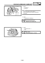
VALVES AND VALVE SPRINGS

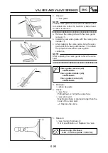
CHECKING THE VALVE SPRINGS

The following procedure applies to all of the valve
springs.

1. Measure:

• spring free length  

a

Out of specification 

-->

 Replace.

2. Measure:

• compressed spring force 

a

Out of specification 

-->

 Replace.

b

 Installed length

3. Measure:

• spring tilt 

a

Out of specification 

-->

 Replace.

Spring tilt limit (all)

2.5

o

/1.6 mm (2.5°/0.063 in)

a

Spring free length
Intake (inside)

36.17mm (1.424 in)
<limit>: 34.47mm (1.357 in)

Exhaust (inside)

 36.17mm (1.424 in)
 <limit>: 34.47mm (1.357 in)

Intake (outside)

36.63mm (1.442 in)
<limit>: 34.63mm (1.363 in)

Exhaust (outside)

36.63mm (1.442 in)
<limit>: 34.63mm (1.363 in)

a

b

Compressed spring force
Inside

75 ~ 91 N at 30.5 mm
(7.50 ~ 9.10 kgf at 30.5 mm,
17 ~ 20.5 lbf at 1.20 in)

Outside

128.5 ~ 157.9 N at 32.0 mm
(12.85 ~ 15.79 kgf.m at 32.0 mm
29 ~ 36 lbf at 1.26 in)

a

5-28

Summary of Contents for YBR250 2007

Page 1: ...YBR250 SERVICE MANUAL 5D1 F8197 E0 2007 ...

Page 2: ......

Page 3: ... MANUAL 2007 Yamaha Motor da Amazônia Ltda First edition February 2007 All rights reserved Any reproduction or unauthorized use without the written permission of Yamaha Motor da Amazônia Ltda is expressly prohibited ...

Page 4: ...ls Modifi cations and significant changes in specifications or procedures will be forwarded to all authorized Yamaha dealers and will appear in future editions of this manual where applicable NOTE Designs and specifications are subject to change without notice IMPORTANT MANUAL INFORMATION Particularly important information is distinguished in this manual by the following The Safety Alert Symbol me...

Page 5: ...n Chapter 3 PERIODIC CHECKS AND ADJUSTMENTS where the sub section title s appears 3 Sub section titles appear in smaller print than the section title 4 To help identify parts and clarify procedure steps there are exploded diagrams at the start of each removal and disassembly section 5 Numbers are given in the order of the jobs in the exploded diagram A circled number indicates a disassembly step 6...

Page 6: ... Special tool C Tightening torque D Clearance wear limit E Engine speed F Electrical data Symbols G N in the exploded diagrams indi cate the types of lubricants and lubrication points G Engine oil H Gear oil I Molybdenum disulphide oil J Brake fluid K Wheel bearing grease L Lithium soap based grease M Molybdenum disulphide grease N Silicone grease Symbols O P in the exploded diagrams indi cate the...

Page 7: ...CONTENTS 8 7 6 5 4 3 GEN INFO 1 2 PERIODIC CHECKS AND ADJUSTMENTS GENERAL INFORMATION SPECIFICATIONS CHASSIS ELECTRICAL SYSTEM TROUBLESHOOTING ENGINE FUEL INJECTION SYSTEM SPEC CHK ADJ CHAS ENG FI ELEC TRBL SHTG ...

Page 8: ...BEL 1 1 FEATURES 1 2 FEATURES 1 2 FI SYSTEM 1 3 IMPORTANT INFORMATION 1 4 PREPARATION FOR REMOVAL AND DISASSEMBLY 1 4 REPLACEMENT PARTS 1 4 GASKETS OIL SEALS AND O RINGS 1 4 LOCK WASHERS PLATES AND COTTER PINS 1 5 BEARINGS AND OIL SEALS 1 5 CIRCLIPS 1 5 CHECKING THE CONNECTIONS 1 6 SPECIAL TOOLS 1 7 ...

Page 9: ... IDENTIFICATION NUMBER Chassis serial number 1 is stamped into the right side of the steering head pipe VEHICLE IDENTIFICATION MODEL LABEL The model label 1 is affixed to the frame This information will be needed to order spare parts 1 1 1 1 ...

Page 10: ...deliver more performance and cleaner exhaust gases increase it becomes necessary to control the air fuel ratio in a more precise and finely tuned manner To accommodate this need this model has adopted an electronically controlled fuel injection FI system in place of the conventional carburetor system This system can achieve an optimum air fuel ratio required by the engine at all times by using a m...

Page 11: ...lled by the ECU Signals that are input from the throttle position sensor crankshaft position sensor intake air pressure sensor atmospheric pressure sensor intake temperature sensor coolant temperature sensor and O2 sensor enable the ECU to determine the injection duration The injection timing is determined through the signals from the crankshaft position sensor As a result the volume of fuel that ...

Page 12: ...lean all of the parts and place them in trays in the order of disassembly This will speed up assembly and allow for the correct installation of all parts 5 Keep all parts away from any source of fire REPLACEMENT PARTS Use only genuineYamaha parts for all replacements Use oil and grease recommended by Yamaha for all lubrication jobs Other brands may be similar in function and appearance but inferio...

Page 13: ...S After removal replace all lock washers plates 1 and cotter pins After the bolt or nut has been tightened to specification bend the lock tabs along a flat of the bolt or nut CIRCLIPS Before reassembly check all circlips carefully and replace damaged or distorted circlips Always replace piston pin clips after one use When installing a circlip 1 make sure the sharp edged corner 2 is positioned oppo...

Page 14: ...all connections Loosen connection Connect properly 4 Connect lead coupler connector CHECKING THE CONNECTIONS 5 Check continuity with the pocket tester If the pin 1 on the terminal is flattened bend it up Pocket tester 90890 03174 1 6 NOTE Make sure that all connections are tight NOTE If there is no continuity clean the terminals When checking the wire harness perform steps 1 to 3 As a quick remedy...

Page 15: ...o remove crankshaft Sliding hammer 1 Shaft 2 Use to install or remove shafts of rocker arm Valve spring compressor 1 Adapter 2 Use to install or remove valves Ring nut wrench Use to loosen or tighten ring nuts to steering exhaust and shock absorber 90890 01311 Use to adjust valves clearance Adjustment screw wrench 90890 01326 90890 01294 Use to fix or extract bolt from the front suspension rod T h...

Page 16: ...light 90890 03153 90890 03176 Use to measure fuel pump pressure Fuel pressure gauge Fuel pressure adapter 90890 03174 Use to check electrical system Pocket tester Use to fix the flywheel magneto rotor 90890 03079 90890 01519 90890 01520 Rear shock absorber wrench Handle spanner Use together with the socket extensor for adjusting preload of the shock absorber spring 90890 06754 Spark dynamic tester...

Page 17: ...uide installer Use to install valve guides 90890 04066 Valve guide reamer Use to rebore the hole on the new valve guides 90890 04086 Use to fix the clutch holder Clutch hub holder 90890 04101 Use to spin and polish valves Valve polisher Use to extract and install valve guides 90890 04065 FI electronic injection diagnosis 90890 03182 Use to adjust the exhaust gas 1 9 ...

Page 18: ...2 14 CONVERSION TABLE 2 16 GENERAL TIGHTENING TORQUE SPECIFICATION 2 16 TIGHTENING TORQUES 2 17 ENGINE TIGHTENING TORQUES 2 17 CHASSIS TIGHTENING TORQUES 2 19 LUBRICATION POINTS AND LUBRICANT TYPES 2 21 ENGINE 2 21 CHASSIS 2 22 OIL COOLING SYSTEM DIAGRAM 2 23 LUBRICATION FLOW 2 24 LUBRICATION SYSTEM DIAGRAMS 2 25 CABLE ROUTING 2 29 ...

Page 19: ...heelbase Ground clearance Minimum turning radius 2 025 mm 79 724 in 745 mm 29 33 in 1 065 mm 41 93 in 805 mm 31 69 in 1 360 mm 53 54 in 190 mm 7 48 in 2 395 mm 94 29 in Weight Dry With oil and fuel Maximum load total of cargo conductor passenger and accessories 138 0 kg 304 lb 167 0 kg 368 lb 154 0 kg 339 lb 2 1 Model code 5D11 Item Standard Limit ...

Page 20: ...cu in Forward inclined 1 cylinder 74 0 x 58 0 mm 2 91 x 2 28 in 9 8 1 1 300 1 500 r min 70 0 90 0 C Fuel Recommended fuel Full tank capacity Total including reserve tank Reserve Regular Unleaded Gasoline 19 2 L 17 4 Imp gal 20 3 US gal 4 5 L 4 0 Imp gal 4 7 US gal Oil pump Oil pump type Inner rotorto outerrotor tip clearance Outer rotor to oil pump housing clearance Oil pump housing to inner rotor...

Page 21: ...t dimensions exhaust Measurement A Measurement B Maximum camshaft runout Timing chain Model number of links Tensioning system Camshaft Drive system Camshaft dimensions intake Chain drive right 36 890 36 990 mm 1 452 1 456 in 30 111 30 211 mm 1 185 1 189 in 36 891 36 991 mm 1 452 1 456 in 30 092 30 192 mm 1 185 1 189 in DID SCR 0404 SV 104 Automatic 0 030 mm 0 001 in 2 3 ...

Page 22: ... 5 975 mm 0 23464 0 23524 in 6 000 6 012 mm 0 23622 0 23669 in 6 000 6 012 mm 0 23622 0 23669 in 12 036mm 0 4739 in 11 955mm 0 4707 in 5 950 mm 0 23425 in 5 935 mm 0 23366 in 6 042 mm 0 23787 in 6 042 mm 0 23787 in Rocker Rocker shaft Rocker inner diameter Shaft outer diameter Gap between rocker and shaft Valves valve seats valve guides Valve clearance cold Intake Exhaust Valve dimensions Diameter...

Page 23: ...NGINE SPECIFICATIONS Item Standard Limit 0 010 0 037 mm 0 0004 0 0015 in 0 025 0 052 mm 0 0010 0 0020 in 0 90 1 10 mm 0 03 0 04 in 0 90 1 10 mm 0 03 0 04 in 36 17 mm 1 424 in 36 17 mm 1 424 in 36 63 mm 1 442 in 36 63 mm 1 442 in 30 50 mm 1 2008 in 32 00 mm 1 2598 in 75 91 N at 30 5 mm 7 5 9 1 kgf at 30 5 mm 17 20 5 lbf at 1 20 in 128 5 157 9 N at 32 mm 12 85 15 79 kgf at 32 mm 29 35 5 lbf at 1 26 ...

Page 24: ...9 0 31 mm 0 0075 x 0 0122 in 0 030 0 065 mm 0 0011 0 0026 in 74 10 mm 2 917 in 0 05 mm 0 002 in 0 05 mm 0 002 in 0 15mm 0 006 in 17 043 mm 0 6709 in 16 97mm 0 6681 in 0 60mm 0 0236 in 0 10mm 0 004 in Cylinder Cylinder arrangement Bore Taper Out of round Piston Piston to cylinder clearance Diameter D Height H Offset Offset direction Piston pin bore in the piston Diameter Piston pin Outside diameter...

Page 25: ...m runout C Big end side clearance D Balancer Balancer drive method Taper 0 80 x 2 80 mm 0 0315 x 0 1102 in 0 30 0 45 mm 0 0118 0 0177 in 0 020 0 055 mm 0 0008 0 0022 in 1 50 x 2 60 mm 0 0590 x 0 1024 in 0 10 0 35 mm 0 004 0 0137 in 69 25 69 30 mm 2 7264 2 7283 in 0 350 0 650mm 0 013 0 026 in Gear 0 60mm 0 0236 in 0 10mm 0 004 in 0 03 mm 0 0012 in Item Standard Limit 2 7 ...

Page 26: ...ype Clutch release method Clutch cable free play at the end of clutch lever Friction plate Thickness Number of discs Clutch plate Thickness Number of discs Maximum warpage Clutch spring Free lenght Number of springs Transmission Transmission type Primary reduction system Primary reduction ratio Secondary reduction system Secondary reduction ratio Operation Gear ratio 1st 2nd 3rd 4th 5th Item Stand...

Page 27: ...onsumption maximum Output pressure Throttle body Model manufacturer quantity Identification mark Throttle cable free play at the throttle flange 33EHS 3D01 MIKUNI 1 5D1100 3 0 5 0 mm 0 12 0 20 in 2 9 Wet element Electrical 5VK DENSO 3 5 A 250 kPa 1875 2 mmHg 73 825 inHg Fuel injector Model manufacturer Quantity 1100 87F70 AISAN 1 ...

Page 28: ...44 in 1 00mm 0 04 in 0 50mm 0 02 in 0 25mm 0 001 in 1 00mm 0 04 in 0 50mm 0 02 in 0 25mm 0 001 in Frame Frame type Caster angle Trail Front wheel Wheel type Rim Size Material Wheel travel Rim runout Maximum radial runout Maximum lateral runout Axle bending limit Rear wheel Wheel type Rim Size Material Wheel travel Runout Maximum radial runout Maximum lateral runout Axle bending limit Item Standard...

Page 29: ...er and accessories Tubeless 130 70 17M C 62S SPORT DEMON PIRELLI 250 kPa 2 50 kgf cm2 36 psi 250 kPa 2 50 kgf cm2 36 psi Load is total weight of cargo rider passenger and accessories 0 9 mm 0 03 in 0 9 mm 0 03 in Item Standard Limit 2 11 Single disc brake Right hand DOT 4 282 x 4 0 mm 11 x 0 16 in 5 2 mm 0 20 in 5 2 mm 0 20 in 11 0mm 0 43 in 25 4mm x 2 1 in x 2 3 50mm 0 14 in 0 10mm 0 004in 1 50mm...

Page 30: ...type Stopper angle left Stopper angle right Front suspension Suspension type Front fork type Front fork travel Spring Free lenght Installed lenght Spring force K1 Spring stroke K1 Optional spring available Inner tube outer diameter Fork oil Recommended coil Amount Each front staff Level from the top of inner tube and the tube fully compressed without the spring Angular bearing 39 0 39 0 Telescopic...

Page 31: ...8 1 38 in 191 5 mm 7 54 in 1 00mm 0 04 in 0 70mm 0 027 in Rear suspension Suspension type Rear shock absorber Shock absorber assembly travel Spring Free lenght Installed lenght Spring force K1 Spring stroke K1 Optional spring available Swingarm Free play at the end of the swingarm Radial Axial Drive chain Type manufacturer Number of links Drive chain slack Maximum section of 15 links Item Standard...

Page 32: ... Ω at 20 C 68 F A C magneto TLLZ79 DENSO 14 0V 200W 5 000 r min 0 42 0 62 Ω at 20 C 68 F white white white Semiconductor short circuit 14 1 14 9 V 25 A 200 0 V YTX7L BS GS YuASA 12 V 6 0 Ah 1 320 0 60 A Item Standard Limit Halogen bulb 14 V 1 4 W x 1 14 V 1 4 W x 1 14 V 1 4 W x 2 LED 2 14 Bulbs voltage x wattage x quantity Headlight Tail brake light Front turn signal Rear turn signal Auxiliary lig...

Page 33: ...type Starter motor Model manufacturer Power output Armature coil resistance Brushes Overall length Spring force Commutator diameter Mica undercut Starter relay Model manufacturer Maximum amperage Coil resistance Horn Horn type Model manufacurer x quantity Maximum amperage Performance Turn signal relay Relay type Model manufacturer Self canceling device built in Frequency Temperature sensor Model m...

Page 34: ... dry threads Components should be at room temperature GENERAL TIGHTENING TORQUE SPECIFICATIONS A Distance between flats B Outside thread diameter CONVERSION TABLE GENERAL TIGHTENING TORQUE SPECIFICATIONS 10 mm 6 mm 6 0 6 4 3 12 mm 8 mm 15 1 5 11 14 mm 10 mm 30 3 0 22 17 mm 12 mm 55 5 5 40 19 mm 14 mm 85 8 5 61 22 mm 16 mm 130 13 0 94 N m General tightening torque A Nut B Bolt kgf m ft lb 2 16 CONV...

Page 35: ...aft timing display Plug M32 1 4 0 0 4 2 9 Magneto rotor timing display Plug M14 1 4 0 0 4 2 9 Oil hose to radiator Bolt M6 4 10 1 0 7 2 Radiator side brackets Bolt M6 2 7 0 0 7 5 1 Injection body clamp Bolt M4 1 2 0 0 2 1 4 Drive shaft mounting plate Bolt M6 2 10 1 0 7 2 Temperature Sensor M8 1 9 0 0 9 6 6 Injection body junction Bolt M6 2 10 1 0 7 2 Exhaust tube to cylinder head Stud M8 2 15 1 5 ...

Page 36: ... 30mm Bolt M8 5 10 1 0 7 2 Gear cap starting motor Bolt M6 3 10 1 0 7 2 Oil hose on engine Bolt M6 2 10 1 0 7 2 Engine cases L 60mm Bolt M6 2 10 1 0 7 2 L 70mm Bolt M6 3 10 1 0 7 2 L 45mm Bolt M6 4 10 1 0 7 2 L 55mm Bolt M6 3 10 1 0 7 2 Air filter box cover Bolt M6 4 2 0 0 2 1 4 Exhaust pipe and cylinder Nut M8 2 20 2 0 14 Exhaust and central connection footrest Bolt M10 2 20 2 0 14 Exhaust and fo...

Page 37: ... 5 1 Steering head pipe 1 torque Nut M25 1 52 5 2 38 4 Steering head pipe 2 torque Nut M25 1 18 1 8 13 3 Transmission sprocket and rear wheel hub Nut M8 6 43 4 3 31 7 Brake disc and front wheel hub Bolt M8 5 23 2 3 17 0 Front wheel axle Bolt M14 1 59 5 9 43 0 Rear wheel axle Nut M16 1 104 10 4 76 7 Head lamp assembly Bolt M5 2 3 5 0 3 2 6 Handle bar top holder Bolt M8 4 23 2 3 16 9 Relay and arm r...

Page 38: ...8 1 54 5 4 40 Chassis and footrest bracket Bolt M8 4 23 2 3 17 Sprocket cover Bolt M6 3 10 1 0 7 2 Side cover Bolt M5 4 7 0 0 7 5 1 Handle bar terminal Bolt M6 2 4 0 0 4 3 0 Seat lock Bolt M6 2 7 0 0 7 5 1 Air induction valve A I System Bolt M6 2 7 0 0 7 5 1 2 20 NOTE 1 First using the Torque wrench apply a torque of 52 N m 5 2 kgf m 38 4 ft lb on the lower ring nut of the steering head pipe After...

Page 39: ...t Valve stems intake and exhaust Valve stem ends intake and exhaust Balancer shaft Drive shaft cams Oil pump rotor inner and outer Oil bump shaft Clutch gear inner and outer Clutch assembly Primary clutch mounting nut Primary clutch Clutch hub mounting nut Driving rod Transmission gears sprocket and pinion Driving main shaft Gearshift forks Gearshift cam Forks shaft Speed sensor O rings Crankcase ...

Page 40: ...tor rod and rear arm seal lips Brake pedal outer surface Steering head pipe bearings upper and lower Guide inner surface of throttle cable Clutch lever screw surface Side rest mating surface Main pedal pivot Pedal spring end Rear axle outer surface Passenger pedal pivot Caliper piston seal Rubber parts inside the master cylinder Caliper piston dust seal Brake lever retaining bolt Sliding area betw...

Page 41: ...SPEC OIL COOLING SYSTEM DIAGRAM OIL COOLING SYSTEM DIAGRAM 1 Radiator 2 Oil inlet hose 3 Oil outlet hose 4 Seal rings O rings A Hot oil inlet B Cooled oil outlet 2 23 1 B 3 2 A 1 2 4 3 ...

Page 42: ...LOW LUBRICATION FLOW Oil supply with pressure Oil return by gravity and centrifugation 2 24 Crankcase Drive axle Oil filter Crankshaft Main axle Metalic filter Cylinder head Check valve Drive shaft Oil pump Oil radiator ...

Page 43: ...SPEC LUBRICATION SYSTEM DIAGRAMS LUBRICATION SYSTEM DIAGRAMS 1 Oil pump 2 Pump driving gear 3 Strainer oil sub filter 4 Oil level gauge 2 25 1 4 2 3 ...

Page 44: ...SPEC LUBRICATION SYSTEM DIAGRAMS 1 Oil delivery hose 2 Oil return hose 3 Oil pump 4 Strainer oil sub filter 5 Oil filter 2 26 2 5 1 3 4 ...

Page 45: ... pins 2 Seal rings O rings 3 Oil filter 4 Oil pump rotor 1 5 Oil pump driving gear 6 Oil timing tube 7 Oil filter housing A Arrow indicates direction to the oil radiator B Arrow indicates direction from the oil radiator 2 27 6 3 5 A 4 2 B 1 7 ...

Page 46: ...SPEC 1 Valve driving shaft 2 Oil timing tube 3 Screw gasket 4 Main axle 5 Drive axle 6 Clutch lever rod LUBRICATION SYSTEM DIAGRAMS 2 28 1 3 2 3 6 5 4 ...

Page 47: ...le 4 Front brake switch wire harness 5 Handlebar switch wire harness LS 6 Throttle cables 7 Headlight connector 8 Instruments panel wireharness 9 Ignition key wireharness 0 Brake hose A Main wire harness B Front flasher wire harness RS C Front flasher wire harness LS D Auxiliary light wire harness 2 29 D E 7 7 ...

Page 48: ...ward C Fasten the handlebar switch wire harness LS and the clutch switch wire harness with a band Place the band end forward D Put inside the headlight box the wire harnesses of the instruments panel ignition key handlebar switches LS and RS and the front turn indication lights left and right E Pass the wireharness through the lower hole F Route the meter lead wire through the headlight bracket st...

Page 49: ...harness 5 Engine breather hose 6 Air induction valve hose 7 Fuel supply hose 8 Clutch cable 9 Temperature sensor wire harness 0 Starter motor cable A Grounding cable negative B Speed sensor wire harness C Rear brake switch wire harness D O2 sensor wire harness E Grounding wire harness 2 31 G 9 2 1 ...

Page 50: ...arness to the chassis with a plastic band G No slack of lead wire in this region A Fasten the wire harness switch to the handlebar with a plastic band B Taking out lead wire shall be in front of the vehicle C Routethetwothrottlecablesthroughtheinsideportion of the bracket D O2 sensor conector shall be in front of the bracket cable 2 32 G 9 2 1 ...

Page 51: ... supply hose 7 Main wire harness 8 Grounding cable negative 9 Stator wire harness 0 Neutral switch wire A Sidestand switch wire harness B Horn wire harness C Speed sensor wire harness D Air induction hose E Engine breather hose F Rear brake switch wire harness G O2 sensor wire harness H Starter cable I Heat sensor wire harness 2 33 20 30 G H I J ...

Page 52: ...ss through battery box guide E Starter motor lead clamp and negative battery lead clamp F Fix the sidestand switch neutral switch and stator wire harness with a plastic band G Clamp sidestand switch lead wire to pipe H Clamp wire harness to pipe I Clamp horn lead wire to chassi J Route wire harness through headlight stay 2 34 20 30 G H I J ...

Page 53: ...ire harness 6 Starter motor cable 7 Grounding cable negative 8 Fuel pump connector 9 Battery negative cable 0 ECU cable A Grounding wire harness B Seat lock cable C Rear light wire harness A Fix the ECU cable with a plastic band B Fix the ECU cable and the ground wire harness with a plastic band 1 2 3 4 5 6 7 8 9 0 A C B A B ...

Page 54: ...nal contacting the brake calipers stopper C The brake hose must not be assembled twisted bended or forcibly D The upper terminal position of the brake hose must be as shown 1 Front brake hose 2 Front brake master cylinder 3 Lower bracket 4 Front brake calipers 5 Headlight bracket 2 36 1 3 4 A C B 5 2 D D 55º 65º ...

Page 55: ...Y 3 22 CHECKING THE AIR FILTER ELEMENT 3 23 CHECKING THE THROTTLE BODY JUNCTION 3 24 CHECKING THE FUEL HOSE 3 24 CHECKING THE ENGINE BREATHER HOSE 3 25 CHECKING THE EXHAUST SYSTEM 3 25 CHECKING THE OIL RADIATOR 3 26 CHASSIS 3 27 CHECKING THE BRAKE FLUID LEVEL 3 27 CHECKING THE FRONT BRAKE PADS 3 28 BLEEDING THE HYDRAULIC BRAKE SYSTEM 3 28 CHECKING THE FRONT BRAKE HOSE 3 30 ADJUSTING THE REAR BRAKE...

Page 56: ...EM 3 43 CHECKING AND CHARGING THE BATTERY 3 43 CHECKING THE FUSES 3 49 REPLACING THE HEADLIGHT BULB 3 50 REPLACING THE HEADLIGHT AUXILIARY BULB 3 51 ADJUSTING THE HEADLIGHT BEAM 3 51 ADJUSTING THE DIGITAL CLOCK 3 51 ...

Page 57: ...Replac e brak e shoes Check for crac ks or dam age Replac e 9 Wheels Check runout and for dam age 10 T ires Check tread depth and for dam age Replac e if neces sary Check the air press ure Correc t if neces sary 11 Wheel bearings Check bearing for looseness or damage Check the operation and for ex ces sive play Lubricate with molybdenum disulfide grease 13 Driv e chain Check chain s lack alignm en...

Page 58: ...and cable Check operation and free play Adjust the throttle cable free play if necessary Lubricate the throttle grip housing and cable 27 Air induction system Check the air cut off valve reed valve and hose for damage Replace any damaged parts if necessary 28 Muffler and exhaust pipe Check the screw clamp for looseness 29 Lights signals and switches Check operation Adjust the headlight beam ANNUAL...

Page 59: ...nch under the left side cover to release the seat 2 Left right side cover 1 1 3 Safety bar 1 4 Rear light connector 1 Disconnect 5 Tail assembly 1 6 Front fender 1 For instalation reverse the removal procedure 3 3 6 2 5 4 3 1 7 N m 0 7 kgf m 5 1 ft lb 30 N m 3 0 kgf m 22 ft lb 7 N m 0 7 kgf m 5 1 ft lb 7 N m 0 7 kgf m 5 1 ft lb 7 N m 0 7 kgf m 5 1 ft lb 7 N m 0 7 kgf m 5 1 ft lb ...

Page 60: ...t Fuel tank Drain 1 Fuel hose 1 2 Tank left cover 1 3 Tank right cover 1 4 Tank plate 1 5 Damper 1 6 Fuel tank 1 For installation reverse the removal procedure Order Job Part Q ty Remarks Disconnect 3 4 10 N m 1 0 kgf m 7 2 ft lb 2 3 5 6 4 7 N m 0 7 kgf m 5 1 ft lb 7 N m 0 7 kgf m 5 1 ft lb 1 7 N m 0 7 kgf m 5 1 ft lb ...

Page 61: ...ea under where it will be removed NOTE Do not set the fuel tank down so that the installation surface of the fuel pump is directly under the tank Be sure to lean the fuel tank in an upright position NOTE Do not drop the fuel pump or give it a strong shock Do not touch the base section of the fuel sender CAUTION 3 5 CAUTION Although the fuel has been removed from the fuel tank be careful when remov...

Page 62: ...olts in stages in a crisscross pattern and to the specified torque Install the fuel pump as shown in the illustration NOTE When installing the fuel hose make sure that it is securely connected and that the fuel hose connector cover on the fuel hose is in the correct position otherwise the fuel hose will not be properly installed CAUTION Install the fuel hose securely onto the fuel pump until a dis...

Page 63: ...er to FUEL TANK 2 Remove tappet cover intake 1 tappet cover exhaust 2 drive shaft sprocket cap 3 Disconnect Spark plug cap 4 Remove Spark plug 5 Remove timing mark accessing screw 1 crankshaft accessing screw 2 Valve clearance adjustment should be made on a cold engine at room temperature When the valve clearance is to be measured or adjusted the piston must be at top dead center TDC on the compre...

Page 64: ...ing directions to obtain the ideal clearance To place the piston at the Upper Dead Center UDC on the compression time match the I mark c of the sprocket camshaft with the mark d at the cylinder head as shown in the illustration NOTE T T T T T T T T T T T T T T T T T T T T T T T T T T T T T T T T T T T T T T T T T T T T T T T T T T T T T T T T T T T T T T T T T T T T T T T T T T T T T T T T T T T T...

Page 65: ... tappet cover exhaust 12 Install fuel tank Refer to FUEL TANK side covers and cowlings right and left seat Refer to COWLING AND SIDE COVERS ADJUSTING THE VALVE CLEARANCE d Prevent the bolt from moving by holding it and tighten the locknut to the specified torque Locknut 14 N m 1 4 kgf m 10 3 ft lb T T T T T T T T T T T T T T T T T T T T T T T T T T T T T T T T T T T T T T T T T Spark plug 18 N m 1...

Page 66: ...switch to ON 2 Disconnect the self diagnostic signal terminal 1 and connect the injection diagnostic terminal 2 Be sure to set the CO density level to standard and then adjust the exhaust gas volume NOTE Injection diagnostic 90890 03182 DlAG will be indicated on the display 2 The green LED POWER 3 is lighten NOTE V V V V V WARNING Carry out the adjustments after being sure that the battery is full...

Page 67: ...shed button UP or DOWN 10 Turn the starting switch to OFF for canceling the adjusting mode 11 Disconnect the injection diagnostic and reconnect the self diagnostic signal terminal The CO volume adjusted and the low idle rotation are indicated on the display 1 To reduce the CO volume adjusted press DOWN 2 To increase the CO volume adjusted press UP 3 NOTE 1 2 3 3 11 ...

Page 68: ...NG THE THROTTLE CABLE FREE PLAY ADJUSTING THE THROTTLE CABLE FREE PLAY Before adjusting the engine idling speed the air filter case should be clean and the engine should have adequate compression NOTE Inductive tachometer 90890 06760 T T T T T T T T T T T T T T T T T T T T T T T T T T T T T T T T T T T T T T T T T T T T T T T T T T T T T T T T T T T T T T T T T T T T T T T T T T T T T T T T T T 3 ...

Page 69: ...specified throttle cable free play is obtained T T T T T T T T T T T T T T T T T T T T T T T T T T T T T T T T T T T T T T T T T If the specified throttle cable free play cannot be obtained on the carburetor side of the cable use the adjusting nut on the handlebar side NOTE Throttle cable free play at the flange of the throttle grip 3 0 5 0 mm 0 12 0 20 in When the throttle is opened the throttle ...

Page 70: ... Measure Spark plug gap a with a wire Thickness gauge Out of specification Regap T T T T T T T T T T T T T T T T T T T T T T T T T T T T T T T T T T T T T T T T T Before removing the spark plugs blow away any dirt accumulated in the spark plug wells with compressed air to prevent it from falling into the cylinders CAUTION Spark plug type manufacturer DR8EA NGK Spark plug gap 0 6 0 7 mm 0 024 0 028...

Page 71: ...eto Out of firing range Check the ignition system Spark plug 18 N m 1 8 kgf m 13 3 ft lb Before installing the spark plug clean the spark plug and gasket surface NOTE Timing light 2 2 2 2 2 90890 03141 Inductive tachometer 3 3 3 3 3 90890 06760 T T T T T T T T T T T T T T T T T T T T T T T T T T T T T T T T T T T T T T T T T Engine idling speed 1 300 1 500 rpm T T T T T T T T T T T T T T T T T T T...

Page 72: ...everal minutes and then turn it off 3 Disconnect spark plug cap 4 Remove spark plug 5 Install compression gauge 1 Insufficient compression pressure will result in a loss of performance NOTE Before removing the spark plugs use compressed air to blow away any dirt accumulated in the spark plug wells to prevent it from falling into the cylinders CAUTION Compression gauge 90890 03081 3 16 1 ...

Page 73: ...oonful of engine oil into the spark plug bore and measure again Refer to the following table Compression at sea level Standard 1200Kpa 12kg cm2 170 7 psi Minimum 1050Kpa 10 5kg cm2 152 3 psi Maximum 1300Kpa 13 0kg cm2 188 5 psi T T T T T T T T T T T T T T T T T T T T T T T T T T T T T T T T T T T T T T T T T T T T T T T T T T T T T T T T T T T T T T T T T T T T T T T T T T T T T T T T T T 3 3 17 C...

Page 74: ...um level mark a and the maximum level mark b Below the minimum level mark Add the recommended engine oil to the proper level Spark plug 18 N m 1 8 kgf m 13 3 ft lb Before checking the engine oil level wait a few minutes until the oil has settled Do not screw the dipstick 1 when checking the oil level NOTE Stand the vehicle on a suitable stand Make sure the vehicle is upright NOTE 3 18 Recommended ...

Page 75: ...lb Before checking the engine oil level wait a few minutes until the oil has settled NOTE CHANGING THE ENGINE OIL 1 Start the engine warm it up for several minutes and then turn it off 2 Place a container under the engine oil drain bolt 3 Remove Dipstick Oil drain bolt 1 Gasket 4 Drain engine oil completely from the crankcase and oil tank 5 If the oil filter element is also to be replaced perform ...

Page 76: ...h the gasket 8 Fill crankcase with the specified amount of the recommended crankcase Quantity Total amount 1 550L 1 4 Imp qt 1 6 US qt Without oil filter element replacement 1 350L 1 2 Imp qt 1 4 US qt With oil filter element replacement 1 450L 1 3 Imp qt 1 5 US qt Oil drain bolt crankcase 20 N m 2 0 kgf m 14 ft lb 3 20 1 2 3 4 5 2 ...

Page 77: ...ne oil starts to seep from the oil gallery bolt If no engine oil comes out after one minute turn the engine off so that it will not seize d Check the engine oil passages the oil filter and the oil pump Refer to OIL PUMP in Chapter 5 e Start the engine after solving the problem s and check the engine oil pressure again f Tighten the oil gallery bolt to specification T T T T T T T T T T T T T T T T ...

Page 78: ...T T T T T T T T T T T T T T T T T T T T T T T T T T T T T T T T T T T T T T T If the specified clutch cable free play cannot be obtained on the handlebar side of the cable use the adjusting nut on the engine side NOTE Engine side a Remove the protection caps b Loosen the locknut 1 c Turn the adjusting bolt 2 in one of the following directions until the specified clutch cable free play is obtained ...

Page 79: ...f engine parts and may damage the engine Operating the engine without the air filter element will also affect the FI tuning leading to poor engine performance and possible overheating CAUTION 1 Remove seat right side cover Refer to COWLING AND SIDE COVERS 2 Remove air filter case cover right 1 bolts 2 Air filter cover bolt 2 N m 0 2 kgf m 1 4 ft lb 3 23 There is a checking hose 1 in the bottom of ...

Page 80: ...e covers left and right Refer to COWLING AND SIDE COVERS fuel tank Refer to FUEL TANK 2 Check fuel hose 1 Breakage damage Replace Loosen connection Connect 3 Install fuel tank Refer to FUEL TANK side covers left and right seat Refer to COWLING AND SIDE COVERS CHECKING THE THROTTLE BODY JUNCTION 1 Check injection body junction 1 Breakage damage Replace Refer to FUEL INJECTION SYSTEM in Chapter 6 3 ...

Page 81: ...g procedure applies to all of the exhaust pipes mufflers and gaskets 1 Check exhaust pipe 1 muffler 2 Cracks damage Replace gasket 3 Exhaust gas leaks Replace 2 Check tightening torque Exhaust pipe nut 17 5 N m 1 7 kgf m 12 9 ft lb Central mounting bolt 20 N m 2 0 kgf m 14 7 ft lb Muffler rear bolt 40 N m 4 0 kgf m 29 5 ft lb CHECKING THE ENGINE BREATHER HOSE CHECKING THE EXHAUST SYSTEM 3 25 2 3 1...

Page 82: ...OR CHECKING THE OIL RADIATOR 1 Remove seat tank side covers Refer to COWLING AND SIDE COVERS 2 Check oil radiator 1 radiator output hose 2 radiator input hose 3 Cracks damage Replace Refer to OIL COOLING SYSTEM in chapter 5 3 26 1 2 3 ...

Page 83: ...r part be is at the horizontal position NOTE Use only the designated brake fluid Other brake fluids may cause piston seals to deteriorate and provoke leakage and poor performance Refill with the same brake fluid type that is already in the system Mixing brake fluids can result in a harmful chemical reaction leading to a defective performance When refilling be careful not to drop any water into the...

Page 84: ...isassembled a brake hose is loosened disconnected or replaced the brake fuel level is very low brake operation is faulty V V V V V WARNING NOTE Be careful not to spill any brake fluid or allow the brake master cylinder reservoir or brake fluid reservoir to overflow When bleeding the hydraulic brake system make sure there is always enough brake fluid before applying the brake Ignoring this precauti...

Page 85: ...ir c Connect a clear plastic hose 1 tightly to the bleed screw 2 d Place the other end of the hose into a container e Slowly apply the brake several times f Fully pull the brake lever or fully press down the brake pedal and hold it in position g Loosen the bleed screw and let the lever moves up to its limit T T T T T T T T T T T T T T T T T T T T T T T T T T T T T T T T T T T T T T T T T Loosening...

Page 86: ... switch also T T T T T T T T T T T T T T T T T T T T T T T T T T T T T T T T T T T T T T T T T Inside Brake pedal is raised Outside Brake pedal is lowered Brake pedal position top of the rider footrest 29 0 mm 1 14 in 3 30 The following procedure applies to all of the brake hose clamps 1 Check front brake hose 1 Cracks damage wear Replace 2 Check brake hose bracket 2 Loosen Screw the clamp bolt 3 ...

Page 87: ...ut After adjusting the pedal position adjust the brake pedal free play V V V V V WARNING 3 Check brake pedal free play1a Out of specification Adjust Brake pedal free play 15 20 mm 0 6 0 8 in CHECKING THE BRAKE LINING 1 Press the brake pedal 2 Check wear display 1 Indicated at the wear limit line 2 Change the brake linings Refer to REAR WHEEL in chapter 4 3 31 a Turn the adjusting bolt 1 until the ...

Page 88: ... adjusting nut 2 in direction a or b until the rear brake light comes on at the proper time T T T T T T T T T T T T T T T T T T T T T T T T T T T T T T T T T T T T T T T T T T T T T T T T T T T T T T T T T T T T T T T T T T T T T T T T T T T T T T T T T T Brake light comes on sooner Direction a a a a a Direction b b b b b Brake light comes on later The free play increases Clockwise Counterclockwis...

Page 89: ... the specified position is obtained The drive chain slack must be checked at the tightest point on the chain NOTE Securely support the vehicle so that there is no danger of it falling over V V V V VWARNING T T T T T T T T T T T T T T T T T T T T T T T T T T T T T T T T T T T T T T T T T A drive chain that is too tight will overload the engine and other vital parts and one that is too loose can ski...

Page 90: ...s may damage those rings Accordingly use only kerosene for the chain cleaning Wipe the drive chain dry and thoroughly lubricate it with engine oil or chain lubricant that is suitable for non Oring chains Do not use any other lubricant type in the drive chain or they may contain solvents that will harm the O rings Locknut 16 N m 1 6 kgf m 11 8 ft lb Recommended lubricant Engine oil or chain lubrica...

Page 91: ...her upper bracket 3 Securely support the vehicle so that there is no danger of it falling over V V V V VWARNING Place the vehicle on a suitable stand so that the front wheel is elevated NOTE 2 Check Steering head Grasp the bottom of the front fork legs and gently rock the front fork Binding looseness Adjust the steering head 3 Remove handlebar holder screws 1 handlebar holders 2 handlebar 3 1 2 3 ...

Page 92: ... 2 f Install the upper ring nut 3 g Finger tighten the upper ring nut 3 then align the slots of both ring nuts If necessary hold the lower ring nut and tighten the upper ring nut until their slots are aligned h Install the lock washer 1 T T T T T T T T T T T T T T T T T T T T T T T T T T T T T T T T T T T T T T T T T Lower ring nut initial tightening torque 52 N m 5 2 kgf m 38 4 ft lb Do not over ...

Page 93: ...ls 2 Oil leakage Replace 7 Install upper bracket washer steering stem nut 8 Fix steering stem side bolts 9 Install handlebar handlebar upper holders Steering stem nut 110 N m 11 0 kgf m 81 1 ft lb Steering stem side bolt 25 N m 2 5 kgf m 18 4 ft lb Handlebar upper holders 23 N m 2 3 kgf m 16 9 ft lb Securely support the vehicle so that there is no danger of it falling over V V V V V WARNING 1 2 ...

Page 94: ...T T T T T T T T T T T T T T T T T T T T T T T T T T Never go beyond the maximum or minimum adjustment positions CAUTION Securely support the vehicle so that there is no danger of it falling over V V V V V WARNING T T T T T T T T T T T T T T T T T T T T T T T T T T T T T T T T T T T T T T T T T Adjusting positions Minimum 1 Standard 2 Maximum 5 Suspension set wrench 90890 01519 90890 01520 Spring p...

Page 95: ...e adjusted according to the total weight including cargo rider passenger and accessories and the anticipated riding speed Operation of an overloaded vehicle could cause tire damage an accident or an injury NEVER OVERLOAD A VEHICLE V V V V V WARNING Basic weight with oil and a full fuel tank Maximum load Cold tire pressure Up to 90kg load 90kg maximum load 227 5 kPa 2 32 kgf cm2 33 psi 248 kPa 2 53...

Page 96: ...nly Tubeless wheel Tube or tubeless tire It is dangerous to ride with a worn out tire When the tire tread reaches the wear limit replace the tire immediately V V V V VWARNING Do not use a tubeless tire on a wheel designed only for tube tires to avoid tire failure and personal injury from sudden deflation When using tube tires be sure to install the correct tube Always replace a new tire and a new ...

Page 97: ...gh speed V V V V V WARNING CHECKING THE TIRES Front tire Rear tire 3 41 Manufacturer Model Size PIRELLI SPORT DEMON 100 80 17M C 52S Manufacturer Model Size PIRELLI SPORT DEMON 130 70 17M C 62S For tires with brand in the rotation direction 1 Install the tire with the brand pointing to the wheel rotation direction Align the brand 2 with the valve installation point NOTE 1 2 ...

Page 98: ...ck cable operation Rough movement Lubricate Hold the cable end upright and pour a few drops of lubricant into the cable sheath or use a suitable lubricating device NOTE Recommended lubricant Engine oil or a suitable cable lubricant CHECKING AND LUBRICATING THE CABLES The following procedure applies to all of the inner Damaged outer cable may cause the cable to corrode and interfere with its moveme...

Page 99: ...severe burns or permanent eye injury FIRST AID IN CASE OF BODILY CONTACT EXTERNAL Skin Wash with water Eyes Flush with water for 15 minutes and get immediate medical attention INTERNAL Drink large quantities of water or milk followed with milk of magnesia beaten egg or vegetable oil Get immediate medical attention V V V V VWARNING 3 43 This is a sealed battery Never remove the sealing caps because...

Page 100: ...e state of an MF battery can be checked by measuring its open circuit voltage i e the voltage when the positive battery terminal is disconnected No charging is necessary when the open circuit voltage equals or exceeds 12 8 V NOTE 1 Remove seat Refer to COWLING AND SIDE COVERS band 2 Disconnect battery leads from the battery terminals Positive tester probe positive battery terminal Negative tester ...

Page 101: ...the battery charger Make sure the battery charger lead clips are in full contact with the battery terminal and that they are not shorted A corroded battery charger lead clip may generate heat in the contact area and a weak clip spring may cause sparks If the battery becomes hot to the touch at any time during the charging process disconnect the battery charger and let the battery cool before recon...

Page 102: ...age exceeded If the amperage does not exceed the standard charging amperage after 5 minutes replace the battery If the required charging time exceeds 5 hours it is advisable to check the charging amperage after 5 hours If there is any change in the amperage readjust the voltage to obtain the standard charging amperage Leave the battery unused for more than 30 minutes before measuring its open circ...

Page 103: ...5 V This type of battery charger cannot charge an MF battery A variable voltage charger is recommended Leave the battery unused for more than 30 minutes before measuring its open circuit voltage 12 8 V Charging is complete 12 0 12 7 V Recharging is required Under 12 0 V Replace the battery YES NO Leave the battery unused for more than 30 minutes before measuring its open circuit voltage NOTE Set t...

Page 104: ...l battery 7 Connect battery leads to the battery terminals 8 Check battery terminals Dirt Clean with a wire brush Loosen connection Connect properly 9 Lubricate battery terminals CAUTION First connect the positive battery lead 1 and then the negative battery lead 2 3 48 Recommended lubricant Dielectric grease 2 1 ...

Page 105: ...T T T T T T T T T T T T T T T T T T T T T T T T T T T T T T T T T T T T T T T T T T T T T T T T T T T T T T T T T T T T T T T T T T T T T T T T T T T T T T T T T T T T T T T T T CAUTION To avoid a short circuit always set the main switch to OFF when checking or replacing a fuse T T T T T T T T T T T T T T T T T T T T T T T T T T T T T T T T T T T T T T T T T Never use a fuse with amperage rating o...

Page 106: ...connector 7 Install Since the headlight bulb gets extremely hot keep flammable products and your hands away from the bulb until it has cooled down V V V V V WARNING Avoid touching the glass part of the headlight bulb to keep it free from oil otherwise the transparency of the glass the life of the bulb and the luminous flux will be adversely affected If the headlight bulb gets soiled thoroughly cle...

Page 107: ...ys SELECT 2 and RESET 3 simultaneously for 2 seconds or more b When the hour digits start blinking press RESET 3 to set the hour c Press SELECT 2 to fix the hour The minutes digits will blink d Press RESET 3 to set the minutes e Press SELECT 2 to fix the minutes ADJUSTING THE DIGITAL CLOCK 1 Adjust digital clock 1 T T T T T T T T T T T T T T T T T T T T T T T T T T T T T T T T T T T T T T T T T T ...

Page 108: ...THE REAR BRAKE 4 20 INSTALLING THE REAR WHEEL 4 22 REAR WHEEL STATIC BALANCE 4 23 FRONT BRAKE 4 24 FRONT BRAKE PADS 4 24 REPLACING THE FRONT BRAKE PADS 4 25 FRONT BRAKE MASTER CYLINDER 4 28 DISASSEMBLING THE FRONT BRAKE MASTER CYLINDER 4 30 CHECKING THE BRAKE MASTER CYLINDER 4 31 ASSEMBLING AND INSTALLING THE BRAKE MASTER CYLINDER 4 31 FRONT BRAKE CALIPERS 4 34 REMOVING THE FRONT BRAKE CALIPER 4 3...

Page 109: ...67 REMOVING THE REAR SHOCK ABSORBER ASSEMBLY 4 68 CHECKING THE REAR SHOCK ABSORBER ASSEMBLY 4 69 CHECKING THE CONNECTING ARMS AND RELAY ARMS 4 69 INSTALLING THE RELAY ARM 4 69 INSTALLING THE REAR SHOCK ABSORBER ASSEMBLY 4 70 SWINGARM AND DRIVE CHAIN 4 71 REMOVING THE SWINGARM 4 73 CHECKING THE SWINGARM 4 74 REMOVING THE SPROCKET 4 75 REMOVING THE DRIVE CHAIN 4 75 CHECKING THE DRIVE CHAIN 4 75 INST...

Page 110: ...heel axle 1 Refer to REMOVING THE 3 Front wheel FRONT WHEEL and 4 Collar left 1 INSTALLING THE FRONT 5 Collar right 1 WHEEL 6 Brake disc 1 To install reverse the removal procedure Job Part Qt y Remarks Order Place the vehicle on a suitable stand so that the front wheel is elevated NOTE 4 1 4 3 6 5 1 2 54 N m 5 4 kgf m 40 ft lb 23 N m 2 3 kgf m 17 ft lb 59 N m 5 9 kgf m 43 ft lb ...

Page 111: ...AND BRAKE DISC FRONT WHEEL Disassembling the front wheel Remove the parts in the order listed 1 Oil seal 2 2 Bearing 2 3 Collar 1 For assembly reverse the disassembly procedure Job Part Qt y Remarks Order 4 2 1 2 3 2 1 ...

Page 112: ...e wear Replace Refer to CHECKING THE TIRES in chapter 3 Securely support the vehicle so that there is no danger of it falling over V V V V VWARNING Do not operates the brake lever when removing the front wheel NOTE Do not attempt to straighten a bent wheel axle Place the vehicle on a suitable stand so that the front wheel is elevated NOTE Place the vehicle on a suitable stand so that the front whe...

Page 113: ...nment 2 Above the specified limits Replace Radial alignment limit 1 0 mm 0 04 in Lateral alignment limit 0 5 mm 0 02 in After assembling a new tire drive carefully during a period for getting used to the new tire sensation and to fit the tire to the rim Failure to follow these instructions may result in accident with possible injury to the rider or damage to the vehicle V V V V VWARNING 4 4 1 2 ...

Page 114: ...ssembly New New T T T T T T T T T TT T T T TT T TT TT T TT T TT T T T T T T T T T T T T T To prevent damaging the wheel place a rag 2 between the screwdriver and the wheel NOTE Do not contact the wheel bearing inner race 4 4 4 4 4 or balls 5 5 5 5 5 Contact should be made only with the outer race 6 6 6 6 6 CAUTION T T T T T T T T T T T T T T TT T T T T T T T T T T T T TT T T T T T T TT T T Use a s...

Page 115: ...t or right to ensure that the front wheel is balanced c Remove the brake calipers d Keep the gauge in a straight angle to the brake disc surface e Measure the deflection at 3 0mm below the brake disc border 3 Measure front disc thickness Measure the front disk thickness at different points Out of specification Replace Deflection limit maximum 0 10 mm 0 04 in T T T T TT TT T TT T T T TT T TT T T T ...

Page 116: ...sting steps until obtain the brake disc deflection to specification f If the brake disc deflection could not reach the specification replace the disc INSTALLING THE FRONT WHEEL 1 Lubricate oil seal lips T T T T T T T T T TT T T T T T T TT T T T TT T TT T T T T T T T T T T T T T Tighten the brake discs screws in stages and in a crisscross pattern NOTE Brake disc screw 23 N m 2 3 kgf m 17 ft lb LOCT...

Page 117: ...5 9 kgf m 43 ft lb Axle mounting bolt 54 N m 5 4 kgf m 40 ft lb ADJUSTING THE FRONT WHEEL STATIC BALANCING Make sure that the brake hose is properly placed V V V V VWARNING After replacing the tire the wheel or both carry out the front wheel static balancing Adjust the front wheel static balancing with the brake disc installed NOTE 4 8 1 2 ...

Page 118: ...ce again Place the front wheel over a suitable stand for balancing NOTE 3 Adjust wheel static balancing a Install a balancing weight 1 to the wheel at the exactly opposite place to the x weight point b Rotate the wheel at 90o so that the weight point be positioned as shown c If the weight point do not reach this position install a larger weight d Repeat steps b and c until the front wheel is balan...

Page 119: ...Nut 1 2 Brake torque rod 1 Loosen 3 Adjusting nut 1 4 Brake rod spring 1 5 Washer 1 6 Brake lever pin 1 7 Brake rod 1 Release 8 Locknut 2 Job Part Qt y Remarks Order Place the vehicle on a suitable stand so that the rear wheel is elevated NOTE 4 10 D C E 2 6 4 5 7 9 8 F F 8 9 B A 0 A 104 N m 10 4 kgf m 76 7 ft lb 16 N m 1 6 kgf m 11 8 ft lb 49 N m 4 9 kgf m 36 ft lb 3 1 ...

Page 120: ...wheel axle 1 13 Rear wheel assembly 1 Refer to REMOVING THE REAR WHEEL and INSTALLING THE REAR WHEEL 14 Left collar 1 15 Right collar 1 16 Chain puller 2 For installation reverse the removal procedure Job Part Qt y Remarks Order 4 11 D C E 2 6 4 5 7 9 8 F F 8 9 B A 0 A 104 N m 10 4 kgf m 76 7 ft lb 16 N m 1 6 kgf m 11 8 ft lb 49 N m 4 9 kgf m 36 ft lb 3 1 ...

Page 121: ...order listed 1 Oil seal 1 2 Sprocket mounting nuts 6 3 Sprocket 1 Remove 4 Bearing 1 5 Rear wheel drive hub 1 6 Collar 1 7 Rear wheel drive hub damper 1 For installation reverse the removal procedure Job Part Qt y Remarks Order BRAKE SHOE PLATE AND REAR WHEEL SPROCKET 4 12 7 6 5 4 1 3 2 New 43 N m 4 3 kgf m 31 7 ft lb ...

Page 122: ...SC AND REAR WHEEL SPROCKET Disassembling the rear wheel Remove the parts in the order listed 1 Bearing 2 2 Oil seals 1 3 Collar 1 For assembling reverse the disassembly procedure Job Part Qt y Remarks Order 4 13 WHEEL 2 1 1 3 ...

Page 123: ...E PLATE Disassembling the brake lining Remove the parts in the order listed 1 Brake shoe assembly 1 2 Brake camshaft lever 1 3 Brake shoe wear indicator 1 4 Brake camshaft 1 For assembly reverse the disassembly procedure 4 14 Job Part Qt y Remarks Order 1 4 2 3 ...

Page 124: ...re is no danger of it falling over V V V V V WARNING Place the vehicle on a suitable stand so that the rear wheel is elevated NOTE 2 Loosen locknut 1 adjusting nut 2 3 Remove rear axle nut 3 washer wheel axle 4 washer rear wheel 4 Remove rear brake plate Push the rear wheel forward and remove the drive chain from the rear wheel sprocket NOTE 4 15 1 4 2 3 ...

Page 125: ...ar wheel wheel bearings oil seals Refer to CHECKING THE FRONT WHEEL 2 Check tire rear wheel Refer to CHECKING THE TIRES in chapter 3 3 Measure radial alignment 1 lateral alignment 2 Above the specified limits Replace Radial alignment limit 1 0 mm 0 04 in Lateral alignment limit 0 5 mm 0 02 in 4 16 ...

Page 126: ...h a clean cloth especially the surfaces that contact the sprocket c Install the new sprocket Tighten the self locking nuts in stages and in a crisscross pattern NOTE T T T T T T T TT T T T T T T T T TT T T T TT T T T T T T T T TT T T T T T T Rear wheel sprocket self locking nut 43 N m 4 3 kgf m 31 7 ft lb T T T T T T T T T T T T T T T T T T T T T T T T T T T T TT T T T T T T T T TT CHECKING THE RE...

Page 127: ...rake camshaft 7 CHECKING THE REAR BRAKE 1 Check brake lining plate pivoting pin brake camshaft Damage Replace Remove the linings pulling them out with the pivoting pin 3 and the brake camshaft 4 as support points in the arrow direction NOTE 2 Check brake shoe lining 1 springs 2 Damage Wear Replace When replacing the brake lining also replace the springs NOTE 4 18 1 2 4 3 5 7 6 1 2 ...

Page 128: ...air Brake shoe lining thickness 4 mm 0 16 in Wear limit 2 mm 0 08 in After using the sandpaper clean the remaining particles with a cloth NOTE Replace the linings if damaged or when they reach the wear limit NOTE Oil Use a wet cloth with solvent or thiner Scratches Eliminate polishing with a thin sandpaper 3 Check brake shoe lining surface Glazed areas Remove Use a rough sandpaper 4 19 1 ...

Page 129: ...131mm 5 16 in 2 Install brake shoe lining 1 springs 2 Install the came axle and the pivoting point using some grease Wipe off the grease excess CAUTION When installing the brake shoe linings use the pivoting pin 3 and the brake camshaft 4 as standing points and press the linings following the arrows directions NOTE 4 20 Do not strain nor damage the spring hooks when installing with calipers Do not...

Page 130: ...7 2 ft lb 5 Install rear wheel Reverse the removal procedure Refer to REAR WHEEL BRAKE DISC AND REAR WHEEL SPROCKET When installing the brake shoe wear indicator place the lobes into the brake camshaft groove and align the pointer with the wear display 2 NOTE Make sure that the rear wheel drive hub damper are properly fit to the rear wheel drive hub NOTE 4 21 1 2 3 ...

Page 131: ...ke torque rod nut 5 4 Install brake lever pin washer brake rod spring 6 rear brake pedal adjusting nut Refer to ADJUSTING THE REAR BRAKE PEDAL 5 Adjust drive chain slack Refer to ADJUSTING THE DRIVE CHAIN SLACK in chapter 3 6 Tighten rear wheel axle nut Recommended lubricant Lithium based soap grease Brake torque rod nut 49 N m 4 9 kgf m 36 ft lb Drive chain slack 25 0 35 0 mm 0 98 1 38 in Rear wh...

Page 132: ...L STATIC BALANCE 1 Adjust rear wheel static balance Refer to FRONT WHEEL STATIC BALANCE After replacing the tire wheel or both the rear wheel static balance must be performed Adjust the rear wheel static balance with the sprocket and the hub installed NOTE 4 23 ...

Page 133: ...order listed 1 Brake caliper bolt 2 2 Guide pins 2 Refer to REPLACING THE 3 Brake pads 2 FRONT BRAKE PADS 4 Brake pads springs 1 For installation reverse the removal procedure Job Part Qt y Remarks Order 4 24 4 4 4 4 4 1 1 1 1 1 2 2 2 2 2 3 3 3 3 3 30 N m 3 0 kgf m 22 ft lb 18 N m 1 8 kgf m 13 3 ft lb ...

Page 134: ...r use solvents on internal brake components Use only clean or new brake fluid for cleaning brake components Brake fluid may damage painted surfaces and plastic parts Therefore always clean up any spilt brake fluid immediately Avoid brake fluid coming into contact with the eyes as it can cause serious injury FIRST AID FOR BRAKE FLUID ENTERING THE EYES Flush with water for 15 minutes and get immedia...

Page 135: ...ur finger c Tighten the bleed screw FRONT BRAKE 3 Remove brake pads 4 brake pads spring 4 Measure brake pads wear limit a Out of specification Replace the brake pads as a set Pad wear limit 1 5 mm 0 06 in T T T T T T T T T T T T T T TT T TT T TT TT T TT T T T T T TT T T T T T T 5 Check brake pad guide pins Damage Wear Replace Bleed screw 6 N m 0 6 kgf m 4 4 ft lb Always replace the springs and the...

Page 136: ...the proper level Refer to CHECKING THE BRAKE FLUID LEVEL in chapter 3 9 Check brake lever operation Soft or spongy feeling Bleed the brake system Refer to BLEEDING THE HYDRAULIC BRAKE SYSTEM in chapter 3 Guide pins 18 N m 1 8 kgf m 13 3 ft lb T T T T T T T T T T T T T T TT T T T T T T T T T T T T TT T T T T T T TT T T Install the inner pad with the a detail aligned with the calipers b pin NOTE 4 2...

Page 137: ...nt switch 1 Disconnect 5 Union bolt 1 6 Copper washer 2 7 Brake hose 1 Disconnect 8 Front brake lever 1 9 Brake master cylinder holder 1 10 Brake master cylinder 1 For installation reverse the removal procedure Job Part Qt y Remarks Order Refer to DISASSEMBLING THE FRONT MASTER CYLINDER and INSTALLING THE FRONT MASTER CYLINDER 4 28 4 6 5 7 8 2 3 0 9 1 25 N m 2 5 kgf m 18 5 ft lb 10 N m 1 0 kgf m 7...

Page 138: ...master cylinder Remove the parts in the order listed 1 Dust boot 1 2 Circlip 1 3 Washer 1 4 Brake master cylinder kit 1 5 Brake master cylinder 1 For assembly reverse the disassembly procedure Job Part Qt y Remarks Order 4 29 5 2 1 3 4New New ...

Page 139: ... front switch 1 Before disassembling the brake master cylinder drain the brake system fluid NOTE 2 Remove union bolt 1 copper washers 2 brake hose 3 To collect any remaining brake fluid place a container under the brake master cylinder and the end of the brake hose NOTE 4 30 1 1 2 3 ...

Page 140: ...ear Replace as a set 3 Check brake master cylinder reservoir 1 Cracks Damage Replace master cylinder reservoir cap 2 Cracks Damage Replace 4 Check brake hoses Cracks Damage Wear Replace ASSEMBLING AND INSTALLING THE BRAKE MASTER CYLINDER Brake fluid recommended DOT4 Before installing all internal brake components must be cleaned and lubricated with new brake fluid Never use solvents on internal br...

Page 141: ...hten the upper bolt and then the lower bolt NOTE 2 Install copper washer brake hose union bolt Union bolt 25 N m 2 5 kgf m 18 5 ft lb New Proper brake hose routing is essential to insure safe vehicle operation Refer to CABLE ROUTING in chapter 2 V V V V VWARNING Install the brake hose with the upper terminal in the leaning angle shown Turn the handlebar to the left and right to make sure the brake...

Page 142: ...ter does not enter the brake master cylinder reservoir Water will significantly lower the boiling point of the brake fluid and could cause vapor lock V V V V VWARNING Brake fluid may damage painted surfaces and plastic parts Therefore always clean up any spilt brake fluid immediately CAUTION 4 Bleed brake system Refer to BLEEDING THE HYDRAULIC BRAKE SYSTEM in chapter 3 5 Check brake fluid level Be...

Page 143: ...he front brake caliper Remove the parts in the order listed Brake fluid Drain 1 Brake hose bracket 1 2 Union bolt 1 3 Copper washer 2 Refer to 4 Brake hose 1 Disconnect INSTALLING 5 Brake calipers bolt 2 THE BRAKE 6 Brake calipers assembly 1 CALIPERS For installation reverse the removal procedure Job Part Qt y Remarks Order ...

Page 144: ...liper Remove the parts in the order listed 1 Guide pins 2 2 Brake pads 2 Refer to INSTALLING THE 3 Brake pad spring 1 FRONT BRAKE CALIPERS For assembly reverse the disassembly procedure Job Part Qt y Remarks Order 4 35 1 3 2 6 N m 0 6 kgf m 4 4 ft lb ...

Page 145: ... brake components Only wash the internal components with brake fluid Do not use solvents for cleaning V V V V VWARNING New Before removing the brake caliper drain the brake fluid from the brake systems NOTE Put the end of the brake hose into a container and pump out the brake fluid carefully NOTE 4 36 Brake pads Brake hoses Brake fluid If necessary Every four years Every two years and whenever the...

Page 146: ...er body 2 Cracks damage Replace the brake caliper brake calipers Brake fluid leakage Replace the brake caliper Replace the piston oil seal whenever the caliper is disassembled V V V V VWARNING 2 Check brake calipers bracket Cracks Damage Replace 3 Check oil ports Unblock blowing with compressed air 4 37 1 2 ...

Page 147: ...ad spring 1 brake pads 2 guide pins 3 Refer to REPLACING THE FRONT BRAKE PADS Guide pins 18 N m 1 8 kgf m 13 3 ft lb 4 Install caliper 1 copper washers 2 brake hose 3 union bolt 4 Union bolt 25 N m 2 5 kgf m 18 5 ft lb The hose correct position is important to the rider safety Refer to CABLE ROUTING in chapter 2 V V V V VWARNING New ASSEMBLING THE BRAKE CALIPER 4 38 1 2 New 1 1 2 3 2 3 4 1 ...

Page 148: ...o CABLE ROUTING in chapter 2 V V V V VWARNING When installing the brake hose onto the brake caliper 1 1 1 1 1 make sure the metallic end tube a a a a a touches the brake caliper body stopper b b b b b CAUTION INSTALLING THE BRAKE CALIPER Brake caliper bolts 30 N m 3 0 kgf m 22 ft lb 2 Fill master cylinder reservoir with the specified amount of the recommended brake fluid Recommended brake fluid DO...

Page 149: ...spongy feeling Bleed the brake system Refer to BLEEDING THE HYDRAULIC BRAKE SYSTEM in chapter 3 4 40 Use only the designated brake fluid Other brake fluids may cause the rubber seals to deteriorate causing leakage and poor brake performance Refill with the same type of brake fluid that is already in the system Mixing brake fluids may result in a harmful chemical reaction leading to poor brake perf...

Page 150: ...VERS in chapter 3 3 Front brake caliper 1 1 Refer to REPLACING THE BRAKE PADS Refer to INSTALLING THE FRONT FORK LEGS Job Part Qt y Remarks Order The following procedure applies to the two front fork legs NOTE 4 41 1 5 4 6 4 2 3 6 N m 0 6 kgf m 4 4 ft lb 7 N m 0 7 kgf m 5 1 ft lb 30 N m 3 0 kgf m 22 ft lb 25 N m 2 5 kgf m 18 5 ft lb 30 N m 3 0 kgf m 22 ft lb 7 N m 0 7 kgf m 5 1 ft lb FRONT FORK ...

Page 151: ...nstallation reverse the removal procedure Job Part Qt y Remarks Order Refer to REMOVING THE FRONT FORK LEGS and INSTALLING THE FRONT FORK LEGS 4 42 1 5 4 6 4 2 3 7 N m 0 7 kgf m 5 1 ft lb 30 N m 3 0 kgf m 22 ft lb 6 N m 0 6 kgf m 4 4 ft lb 25 N m 2 5 kgf m 18 5 ft lb 7 N m 0 7 kgf m 5 1 ft lb 30 N m 3 0 kgf m 22 ft lb ...

Page 152: ...LING THE 6 Oil seal clip 1 FRONT FORK LEGS 7 Shock absorber rod bolt Copper washer 1 1 and ASSEMBLING THE FRONT 8 Shock absorber rod 1 FORK LEGS 9 Rebound spring 1 Job Part Qt y Remarks Order The following procedure applies to both front fork legs NOTE 4 43 0 F E 8 7 B A 1 2 3 4 5 6 9 New 23 N m 2 3 kgf m 17 ft lb New New New New New C D 23 N m 2 3 kgf m 17 ft lb ...

Page 153: ...il flow stopper 1 E Inner tube bushing 1 F Outer tube 1 For assembly reverse the disassembly procedure Job Part Qt y Remarks Order Refer to ASSEMBLING THE FRONT FORK LEG 0 F E 8 7 B A 1 2 3 4 5 6 9 New New New New New New C D 4 44 23 N m 2 3 kgf m 17 ft lb 23 N m 2 3 kgf m 17 ft lb ...

Page 154: ...at the front wheel is elevated NOTE 2 Remove brake hose holders 1 3 Loosen upper bracket mounting bolt 1 cap bolt 2 lower bracket mounting bolts 3 Before loosening the upper and lower bracket mounting bolts support the front fork leg V V V V VWARNING 4 Remove front fork legs front brake caliper Refer to FRONT BRAKE DISC AND WHEEL DISASSEMBLING THE FRONT FORK LEGS The following procedure applies to...

Page 155: ...orber rod assembly with the adapter 2 and T handle 3 loosen the shock absorber rod bolt 1 T handle 90890 01326 Adapter 90890 01294 5 Remove inner tube T T T T T T T T T TT T T T TT T TT TT T TT T TT T T T T T T T T T T T T T a Hold the front fork leg horizontally b Slowly push the inner tube into the outer tube and just before it bottoms out pull the inner tube back quickly c Repeat this step unti...

Page 156: ...TION T T T T T T T T T T T T T T TT T T T T T T T T T T T T TT T T T T T T TT T T CHECKING THE FRONT FORK LEGS The following procedure applies to both front fork legs 1 Check inner tube 1 outer tube 2 Damage Scratches Replace Do not attempt to align a bent inner tube as this may dangerously weaken it V V V V VWARNING 2 Measure spring free length a Out of specification Replace Spring free lenght 48...

Page 157: ...llowing parts inner tube bushing outer tube bushing oil seal boot Before assembling the front fork leg make sure all of the components are clean NOTE 1 Install shock absorber rod 1 rebound spring 2 4 48 The front fork leg has a built in damper adjusting rod and a very sophisticated internal construction which are particularly sensitive to foreign material When disassembling and assembling the fron...

Page 158: ...ng 23 N m 2 3 kgf m 17 ft lb LOCTITE R 4 Install outer tube bushing 1 with the sliding installer to the fork retainer 3 and adapter 4 washer 2 New While holding the damper rod assembly with the shock absorber rod holder 2 and the T handle 3 tighten the shock absorber rod assembly bolt 1 NOTE Leg retainer installer 90890 01367 Adapter 90890 01371 1 n New 4 49 1 2 3 3 4 2 1 New ...

Page 159: ...s lips with lithium soap based grease Lubricate the outer surface of the inner tube with fork oil Cover the top of the front fork leg with a plastic bag 3 to protect the oil seal during installation NOTE 6 Install oil seal clip 1 Adjust the oil seal clip so that it fits into the outer tube s groove NOTE 7 Install boot 1 Leg retainer installer 90890 01367 Adapter 90890 01371 4 50 1 2 3 1 1 ...

Page 160: ... of the inner tube with the inner tube fully compressed and without the spring 123 0 mm 4 8 in While filling the front fork leg keep it upright After filling slowly rock the front fork leg upward and downward to spread the fork oil NOTE 10 Install spring 1 spacer 2 o ring cap bolt 3 New 4 51 Install the spring with the bigger pitch facing up Before installing the cap bolt lubricate its o ring with...

Page 161: ...e front fork leg align the inner tube with its upper end exceeding the upper bracket top in 1 0 mm NOTE 2 Tighten leg cap bolt 1 lower bracket mounting bolt upper bracket mounting bolt 2 Leg cap bolt 23 N m 2 3 kgf m 17 ft lb Make sure that the brake hose is properly installed V V V V VWARNING Mounting bolts Lower bracket 30 N m 3 0 kgf m 22 ft lb Upper bracket 25 N m 2 5 kgf m 18 5 ft lb 4 52 2 1...

Page 162: ...0 7 kgf m 5 1 ft lb Proper brake hose routing is essential to insure safe vehicle operation Refer to CABLE ROUTING in chapter 2 V V V V VWARNING 4 Install bolts brake caliper Bolts brake caliper 30 N m 3 0 kgf m 22 ft lb 5 Install front wheel Refer to FRONT BRAKE DISC AND WHEEL 4 53 1 1 ...

Page 163: ...ght switch 1 Disconnect Refer to REMOVING THE 4 Brake master cylinder holder 1 HANDLEBAR 5 Brake master cylinder 1 6 Grip end 2 Refer to INSTALLING THE 7 Right handlebar switch 1 HANDLEBAR 8 Throttle cable 2 Job Part Qt y Remarks Order 4 54 8 7 9 6 1 5 3 4 2 E 2 1 0 B C F D 6 A 4 N m 0 4 kgf m 3 0 ft lb 23 N m 2 3 kgf m 17 ft lb 4 N m 0 4 kgf m 3 0 ft lb ...

Page 164: ...to REMOVING THE HANDLEBAR and INSTALLING THE HANDLEBAR 15 Handlebar upper holder 2 Refer to INSTALLING THE 16 Handlebar 1 HANDLEBAR For installation reverse the removal procedure Job Part Qt y Remarks Order Refer to INSTALLING THE HANDLEBAR 4 55 8 7 9 6 1 5 3 4 2 E 2 1 0 B C F D 6 A 23 N m 2 3 kgf m 17 ft lb 4 N m 0 4 kgf m 3 0 ft lb 4 N m 0 4 kgf m 3 0 ft lb ...

Page 165: ...ndlebar and the handlebar grip and gradually push the grip off the handlebar NOTE CHECKING THE HANDLEBAR 1 Check handlebar 1 Seizure Scratches Damage Replace Do not attempt to straighten a bent handlebar as this may dangerously weaken it V V V V VWARNING INSTALLING THE HANDLEBAR 1 Stand the vehicle on a level surface Securely support the vehicle so that there is no danger of it falling over V V V ...

Page 166: ...T T TT T TT T T T T T T T T T T T T T a Lubricate the handlebar left end with a thin coat of rubber seal b Slide the grip through the handlebar left end c Wipe off any rubber seal excess with a clean cloth Do not touch the handlebar lever until the rubber seal is completely dry V V V V VWARNING T T T T T T T T T T T T T T TT T T T T T T T T T T T T TT T T T T T T TT T T There must be a 1 to 3 mm f...

Page 167: ...bar switch 2 grip end 3 Grip end bolt 4 N m 0 4 kgf m 3 0 ft lb Lubricate the inner part of the throttle grip with a thin coat of lithium soap based grease and install it to the handlebar Route the throttle cables through the groove into the right handlebar switch and then install the cables Align the projection a on the right handlebar switch with the hole b on the handlebar There must be a 1 to ...

Page 168: ...t clutch cable free play Refer to ADJUSTING THE CLUTCH CABLE FREE PLAY in chapter 3 Clutch cable free play on the clutch lever end 10 0 15 0 mm 0 4 0 6 in 10 Adjust throttle cable free play Refer to ADJUSTING THE THROTTLE CABLE FREE PLAY in chapter 3 Throttle cable free play in the grip 3 0 5 0 mm 0 12 0 20 in 4 59 ...

Page 169: ...RONT FORK Handlebar Refer to HANDLEBAR Front fender 1 Steering stem nut 1 2 Washer 1 Refer to REMOVING THE 3 Upper bracket 1 LOWER BRACKET and 4 Lock washer 1 INSTALLING THE HEAD 5 Upper ring nut 1 STEERING 6 Rubber washer 1 Job Part Qt y Remarks Order 4 60 8 B A 9 6 0 7 5 4 3 2 1 110 N m 11 0 kgf m 81 ft lb 1st 52 N m 5 2 kgf m 38 4 ft lb 2nd 18 N m 1 8 kgf m 13 3 ft lb ...

Page 170: ...RING 9 Bearing cover 1 HEAD 10 Upper bearing 1 Refer to INSTALLING THE 11 Lower bearing 1 STEERING HEAD 12 Seal bearing 1 For installation reverse the removal procedure Job Part Qt y Remarks Order 4 61 8 B A 9 6 0 7 5 4 3 2 1 110 N m 11 0 kgf m 81 ft lb 1st 52 N m 5 2 kgf m 38 4 ft lb 2nd 18 N m 1 8 kgf m 13 3 ft lb ...

Page 171: ...ndlebar nut wrench 3 tighten the lower ring nut and remove the upper ring nut with the ring nut wrench 4 NOTE Steering nut wrench 90890 01403 Ring nut wrench 90890 01268 Securely support the lower bracket so that there is no danger of it falling V V V V VWARNING CHECKING THE STEERING HEAD 1 Wash bearing cover upper bearing lower bearing Recommended cleaning solvent Kerosene 2 Check bearing cover u...

Page 172: ...new bearing races T T T T T T T T T T T T T T TT T T T T T T T T T T T T TT T T T T T T TT T T 4 Check upper bracket lower bracket along with the steering head Bends Cracks Damage Replace INSTALLING THE STEERING HEAD 1 Lubricate bearing cover upper bearing lower bearing Recommended lubricant Lithium soap based grease 2 Install lower ring nut 1 rubber washer 2 upper ring nut 3 lock washer 4 Refer t...

Page 173: ...ont fork legs Refer to INSTALLING THE FRONT FORK LEGS Temporarily tighten the lower bracket NOTE 5 Tighten steering stem nut Steering stem nut 110 N m 11 0 kgf m 81 ft lb 6 Install handleabr handlebar upper holders Refer to HANDLEBAR 7 Tighten handlebar upper holder nuts Upper holder nuts 23 N m 2 3 kgf m 17 ft lb 4 64 ...

Page 174: ...ase COVERS in chapter 3 Rear wheel Refer to REAR WHEEL BRAKE DISC AND REAR WHEEL SPROCKET 1 Self locking nut washer bolt 2 2 2 Refer to REMOVING THE 2 Connecting arm 2 REAR SHOCK ABSORBER 3 Oil seal bushing spacer 2 1 1 ASSEMBLY and INSTALLING THE REAR SHOCK ABSORBER ASSEMBLY Job Part Qt y Remarks Order 4 65 1 2 3 0 A 9 5 9 A 3 0 2 1 1 6 6 8 4 4 7 58 N m 5 8 kgf m 42 8 ft lb 7 58 N m 5 8 kgf m 42 ...

Page 175: ... bolt 1 1 1 THE REAR SHOCK ABSORBER 8 Rear shock absorber assembly 1 ASSEMBLY 9 Oil seal bushing spacer 2 1 1 10 Oil seal bushing spacer 2 1 1 Refer to INSTALLING THE 11 Oil seal bushing spacer 2 1 1 RELAY ARM For installation reverse the removal procedure Job Part Qt y Remarks Order 4 66 1 2 3 0 A 9 5 9 A 3 0 2 1 1 6 6 8 4 4 7 7 58 N m 5 8 kgf m 42 8 ft lb 58 N m 5 8 kgf m 42 8 ft lb 58 N m 5 8 k...

Page 176: ...ck absorber Do not subject the rear shock absorber to an open flame or any other source of high heat High heat can cause an explosion due to excessive gas pressure Do not deform or damage the rear shock absorber in any way If the rear shock absorber is damaged damping performance will suffer V V V V VWARNING Gas pressure must be released before disposing of a rear shock absorber and gas cylinder T...

Page 177: ...and so that the rear wheel is elevated NOTE 2 Remove connecting arm bolt 1 lower bolt of the rear shock absorber assembly 2 While removing the rear shock absorber assembly lower bolt hold the swingarm so that it does not drop down NOTE 3 Remove upper bolt of the rear shock absorber assembly rear shock absorber assembly Raise the swingarm and then remove the rear shock absorber assembly from betwee...

Page 178: ... Replace the rear shock absorber assembly bolts Bents Damage Wear Replace CHECKING THE CONNECTING ARMS AND RELAY ARMS 1 Check connecting arms 1 relay arms 2 Damage Wear Replace 2 Check spacers oil seals bushings Damage Pitting Scratches Replace INSTALLING THE RELAY ARM 1 Install bushing 1 in the relay arm and rear swingarm bushing 2 in the relay arm 3 Rear swingarm 4 Rear shock absorber 5 Relay ar...

Page 179: ...he rear shock absorber assembly Lower nut of the rear shock absorber assembly relay arm nut chassis relay arm nut connecting arm connecting arm nut rear swingarm Upper nut 58 N m 5 8 kgf m 42 8 ft lb Lower nut 58 N m 5 8 kgf m 42 8 ft lb Relay arm nut 58 N m 5 8 kgf m 42 8 ft lb Connecting arm nut 58 N m 5 8 kgf m 42 8 ft lb Connecting arm nut 58 N m 5 8 kgf m 42 8 ft lb 4 Adjust chain slack Refer...

Page 180: ...bsorber DISC AND REAR WHEEL SPROCKET Refer to REAR SHOCK ABSORBER 1 Shift pedal pivot 1 Loosen 2 Drive sprocket cover 1 3 Drive sprocket nut 1 4 Lock washer 1 5 Drive sprocket 1 6 Drive chain 1 Refer to REMOVING THE DRIVE CHAIN Job Part Qt y Remarks Order 4 71 58 N m 5 8 kgf m 42 8 ft lb 0 AB 8 1 110 N m 11 0 kgf m 81 ft lb 3 4 5 6 2 58 N m 5 8 kgf m 42 8 ft lb 7 0 C B A 9 ...

Page 181: ...ingarm 1 10 Cover 2 11 Washer 2 Refer to INSTALLING THE 12 Bearing 2 REAR SWINGARM 13 Spacer 1 For installation reverse the removal procedure Job Part Qt y Remarks Order 4 72 58 N m 5 8 kgf m 42 8 ft lb 0 AB 8 1 110 N m 11 0 kgf m 81 ft lb 3 4 5 6 2 58 N m 5 8 kgf m 42 8 ft lb 7 0 C B A 9 ...

Page 182: ...D DRIVE CHAIN REMOVING THE SWINGARM 1 Stand the vehicle on a level surface Securely support the vehicle so that there is no danger of it falling over V V V V VWARNING Place the vehicle on a suitable stand so that the rear wheel is elevated NOTE 2 Measure swingarm side play swingarm vertical movement T TT T TT TT T TT T T T TT T TT T T T T T T T T T T T T T T T T T T T T T Rear swingarm shaft nut 5...

Page 183: ...ft Roll the rear swingarm shaft on a level surface Bends Replace Do not attempt to straighten a bent pivot shaft V V V V VWARNING 3 Wash swingarm shaft dust seals spacer bushing bearing Recommended cleaning solvent Kerosene 4 Check Dust seals spacers oil seals Damage Wear Replace bushings Damages Pitting Replace 4 74 ...

Page 184: ...upport the vehicle so that there is no danger of it falling over V V V V VWARNING Place the vehicle on a suitable stand so that the rear wheel is elevated NOTE 2 Remove drive chain CHECKING THE DRIVE CHAIN 1 Measure The 15 links length in the inner part a and the outer part b in the roller and calculate the length between the central rollers Length c between central rollers inner dimension a outer...

Page 185: ... between the drive chain side plate Never use high pressure water or air steam gasoline certain solvents e g benzine or a coarse brush to clean the drive chain High pressure methods could force dirt or water into the drive chain s internals and solvents will deteriorate the O rings A coarse brush can also damage the O rings Therefore use only kerosene to clean the drive chain Do not dip the drive ...

Page 186: ...from the drive chain and below the rear swingarm SWINGARM AND DRIVE CHAIN 5 Lubricate drive chain Recommended lubricant Engine oil or chain lubricant suitable for non O ring chains 6 Check drive sprocket driven sprocket More than 1 4 tooth a wear Replace the drive sprocket and the driven sprocket as a set Bent teeth Replace the drive sprocket and the driven sprocket as a set b Correct 1 Chain roll...

Page 187: ...ium soap based grease 2 Install bushing 1 bearings 2 washers 3 3 Install swingarm swingarm shaft swingarm shaft nut Rear swingarm shaft nut 58 N m 5 8 kgf m 42 8 ft lb 4 Install connecting arm bolt washer connecting arm nut rear wheel Refer to INSTALLING THE REAR WHEEL Connecting arm nut 58 N m 5 8 kgf m 42 8 ft lb 4 78 1 2 3 ...

Page 188: ...nut 3 New Drive sprocket nut 110 N m 11 0 kgf m 81 0 ft lb 6 Bend the lock washer tab a at the drive sprocket nut side 7 Adjust drive chain slack Refer to ADJUSTING THE DRIVE CHAIN SLACK in chapter 3 Drive chain slack 25 0 35 0 mm 1 0 1 4 in 8 Adjust shift pedal position Refer to ADJUSTING THE SHIFT PEDAL POSITION in chapter 3 Shift pedal position Top of the rider footrest 30 0 mm 1 18 in 4 79 1 1...

Page 189: ... 19 VALVES AND VALVE SPRINGS 5 21 REMOVING THE VALVES 5 23 CHECKING THE VALVES AND VALVE GUIDES 5 24 CHECKING THE VALVE SEAT 5 26 CHECKING THE VALVE SPRINGS 5 28 INSTALLING THE VALVES 5 28 CYLINDER AND PISTON 5 30 REMOVING THE CYLINDER AND PISTON 5 31 CHECKING THE CYLINDER AND PISTON 5 31 CHECKING THE PISTON RINGS 5 33 CHECKING THE PISTON PIN 5 34 INSTALLING THE CYLINDER AND PISTON 5 35 CLUTCH 5 3...

Page 190: ...HECKING THE STOPPER LEVER 5 61 INSTALLING THE SHIFT SHAFT 5 61 STARTER CLUTCH AND AC MAGNETO 5 63 REMOVING THE AC MAGNETO 5 65 CHECKING THE STARTER CLUTCH ONE WAY 5 66 ASSEMBLING THE AC MAGNETO 5 66 CRANKSHAFT AND CRANKCASES 5 69 DISASSEMBLING THE CRANKCASES 5 71 REMOVING THE BALANCER AND CRANKSHAFT ASSEMBLY 5 72 CHECKING THE CRANKSHAFT 5 72 CHECKING THE CRANKCASES 5 73 CHECKING THE TIMING CHAIN G...

Page 191: ...ffler and the exhaust pipes Remove the parts in the order listed 1 Muffler 1 2 Exhaust pipe 1 3 Gasket 1 For installation reverse the removal procedure Job Part Qt y Remarks Order 5 1 40 N m 4 0 kgf m 30ft lb 17 5 N m 1 7kgf m 12 9 ft lb 1 2 3 20 N m 2 0 kgf m 15 ft lb New ...

Page 192: ... COWLING AND SIDE COVERS in chapter 3 Fuel tank side covers right and left fuel tank Refer to FUEL TANK in chapter 3 Throttle body assy Refer to INJECTION BODY ASSEMBLY in chapter 6 1 Shift pedal 1 Refer to DRIVE CHAIN in chapter 4 2 Drive sprocket 1 Job Part Qt y Remarks Order 1 B 3 2 8 9 0 C 4 A 5 6 7 10 N m 1 0 kgf m 7 2 ft lb 5 2 10 N m 1 0 kgf m 7 2 ft lb 110 N m 11 0 kgf m 81 ft lb 30 N m 3 ...

Page 193: ...ire harness connectors 5 Disconnect 9 Spark plug cap 1 10 Ignition coil 1 11 Vacuum hose 1 Disconnect 12 Neutral switch wire 1 Disconnect 13 Speed sensor wire harness 1 Disconnect Job Part Qt y Remarks Order 1 B 3 2 8 9 0 C 4 A 5 6 7 5 3 10 N m 1 0 kgf m 7 2 ft lb 110 N m 11 0 kgf m 81 ft lb 10 N m 1 0 kgf m 7 2 ft lb 30 N m 3 0 kgf m 22 ft lb New ...

Page 194: ...1 ENGINE 4 Bolt nut lower rear 1 1 REMOVING THE ENGINE ENGINE Install all the bolts and nuts and tighten them to the specified torque CAUTION Job Part Qt y Remarks Order Place a suitable stand under the chassi NOTE 5 4 6 3 8 8 1 5 65 N m 6 5 kgf m 48 ft lb 9 4 2 7 65 N m 6 5 kgf m 48 ft lb 65 N m 6 5 kgf m 48 ft lb 30 N m 3 0 kgf m 22 ft lb 30 N m 3 0 kgf m 22 ft lb ...

Page 195: ...rackets 2 THE ENGINE 9 Upper brackets 2 For installation reverse the removal procedure Job Part Qt y Remarks Order Remove the engine from the right side of the vehicle NOTE 5 5 6 3 8 8 1 5 65 N m 6 5 kgf m 48 ft lb 9 4 2 7 65 N m 6 5 kgf m 48 ft lb 65 N m 6 5 kgf m 48 ft lb 30 N m 3 0 kgf m 22 ft lb 30 N m 3 0 kgf m 22 ft lb ...

Page 196: ...pper bracket mounting bolt nut 3 upper rear mounting bolt nut 4 lower front mounting bolt nut 5 lower rear mounting bolt nut 6 bolt nut upper rear 7 Lower front mounting bolt nut 65 N m 6 5 kgf m 48 ft lb Lower rear mounting bolt nut 65 N m 6 5 kgf m 48 ft lb Lower rear mounting bolt nut 65 N m 6 5 kgf m 48 ft lb Bracket bolts nuts 30 N m 3 0 kgf m 22 ft lb Upper rear mounting bolt nut 65 N m 6 5 ...

Page 197: ...exhaust 1 1 4 Tappet cover O ring intake 1 1 Refer to REMOVING THE 5 Breather hose 1 CYLINDER HEAD and 6 Crankshaft plug 1 INSTALLINGTHE CYLINDER HEAD Job Part Qt y Remarks Order 5 7 E C G F 1 3 60 N m 6 0 kgf m 44 ft lb B 8 A 10 N m 1 0 kgf m 7 2 ft lb 2 18 N m 1 8 kgf m 13 ft lb 4 0 9 7 5 N m 0 75 kgf m 5 5 ft lb 7 6 22 N m 2 2 kgf m 16 ft lb 20 N m 2 0kgf m 14 ft lb 5 10 N m 1 0 kgf m 7 2 ft lb...

Page 198: ...14 Timing Chain guide front 1 INSTALLINGTHE CYLINDER 15 Dowel pins 2 HEAD 16 Cylinder head gasket 1 For installation reverse the removal procedure Job Part Qt y Remarks Order 5 8 E C G F 1 3 60 N m 6 0 kgf m 44 ft lb B 8 A 10 N m 1 0 kgf m 7 2 ft lb 2 18 N m 1 8 kgf m 13 ft lb 4 0 9 7 5 N m 0 75 kgf m 5 5 ft lb 7 6 22 N m 2 2 kgf m 16 ft lb 20 N m 2 0kgf m 14 ft lb 5 10 N m 1 0 kgf m 7 2 ft lb 10 ...

Page 199: ...y pointer d at the head cylinder T T T T T T T T T T T T T T TT T T T T T T T T T T T T TT T T T T T T TT T T 2 Loosen timing sprocket bolt 1 3 Loosen timing chain tensioner bolts 1 4 Remove timing chain tensioner with the gasket camshaft sprocket 5 Remove cylinder head Loosen the bolts in the correct sequence as shown by 1 2 3 4 5 and 6 Loosen each bolt 1 2 of a turn at a time When all the bolts ...

Page 200: ...Maximum runout 0 03 mm 0 001 in T T T T T T T T T T T T T T TT T TT TT T TT T TT T T T T T T T T T T T T T a Place a ruler 1 and a thickness gauge 2 along the cylinder head b Measure the runout c When the limit is exceed rebore the cylinder d With a thin sandpaper 400 to 600 grainy is applied to the cylinder head surface carry out the grinding making movements following the 8 shape To ensure a lev...

Page 201: ...ace 2 Check one way came operation Rough movement Replace 3 Check timing chain tensioner bolt gasket timing chain tensioner rod Damage Wear Replace 4 Check lock and release the operation Rough movement Replace CHECKING THE CAMSHAFT SPROCKET 1 Check camshaft sprocket Wear Damage Replace the sprocket and the timing chain as a set 1 Drive chain 2 Camshaft sproket 2 Check timing chain guide front Dama...

Page 202: ...R 17mm 1 2 3 and 4 Cylinder head bolts 20 N m 2 0 kgf m 14 ft lb Cylinder head bolts 22 N m 2 2 kgf m 16 ft lb 5 6 1 4 3 2 5 12 New New Lubricate the threads and the mating surface of the cylinder head bolts with engine oil Install the washers with its rounded surface turned to the bolt bottom NOTE Tighten the cylinder head bolts in the specified sequence as shown and then tighten them in two stag...

Page 203: ...haft to prevent damages or incorrect valve timing CAUTION T T T T T T T T T T T T T T TT T T T T T T T T T T T T TT T T T T T T TT T T 5 Install timing chain tensioner T T T T T T T T T T T T T T TT T TT TT T TT T TT T T T T T T T T T T T T T a While gently finger tightening the timing chain tensioner rod use a screwdriver 1 to fully spin the shaft clockwise b With the rod totally removed install ...

Page 204: ... Out of alignment Correct Repeat the steps 4 to 7 if necessary Check if the I mark in the AC magneto is aligned with the stationary pointer b on the AC magneto cover NOTE Check if the I mark on the timing sprocket is aligned with the pointer d on the cylinder head NOTE 1 2 a b d c 5 14 Bolts cam chain puller 10 N m 1 0 kgf m 7 2 ft lb Cap bolt cam chain puller 7 5 N m 0 75 kgf m 5 5 ft lb ...

Page 205: ... 8 Tighten timing sprocket bolt 1 Timing sprocket bolt 60 N m 6 0 kgf m 44 ft lb 9 Measure valve clearance Out of specification Adjust Refer to ADJUSTING THE VALVE CLEARANCE in chapter 3 CYLINDER HEAD 5 15 ...

Page 206: ...knut 2 2 3 Camshaft 1 4 Rocker shaft intake 1 5 Rocker arm intake 1 6 Rocker shaft exhaust 1 7 Rocker arm exhaust 1 For installation reverse the removal procedure Job Part Qt y Remarks Order CAUTION Do not disassemble the camshaft assembly Refer to REMOVINGTHE ROCKER ARMS AND CAMSHAFT and INSTALLING THE CAMSHAFT AND ROCKER ARMS 5 16 3 1 6 7 4 5 2 10 N m 1 0 kgf m 7 2 ft lb 14 N m 1 4 kgf m 10 3 ft...

Page 207: ... cames Blue color Pitting Scratches Replace the camshaft and the timing sprocket 4 Remove camshaft 1 bearing 2 1 2 5 17 3 Remove intake rocker shaft exhaust rocker shaft intake rocker arm exhaust rocker arm 1 2 Sliding hammer 90890 01084 Shaft 90890 01083 Remove the rocker shafts with the sliding hammer 1 and the shaft 2 NOTE Use a bolt with thread of 10mm to pull the camshaft out NOTE ...

Page 208: ...ating surface 1 adjusting bolts mating surfaces 2 Damage Wear Replace The following procedures applie to the rocker arms and rocker shafts 2 Check rocker shaft Blue discoloration Excessive wear Pitting Scratches Replace and check the lubrication system a b 1 2 2 Camshaft came dimensions Intake a a a a a 36 890 36 990mm 1 452 1 456 in b b b b b 30 111 30 211mm 1 185 1 189 in Exhaust a a a a a 36 89...

Page 209: ... outer diameter 11 981 11 991mm 0 4717 0 4721 in limit 11 955mm 0 4707 in INSTALLING THE ROCKER ARMS AND CAMSHAFT 1 Lubricate camshaft bearing Recommended lubricant Camshaft Molybdenum disulfide oil Bearing Engine oil 2 Apply molybdenum disulfide oil in the rocker arm and rocker shaft Recommended lubricant Molybdenum disulfide 3 Install rocker arm 1 rocker shaft 2 Use the sliding hammer shaft to i...

Page 210: ...ing 2 5 Apply molybdenum disulfide oil Recommended lubricant Molybdenum disulfide oil 6 Install camshaft holder 1 bolts Holder bolts 10 N m 1 0 kgf m 7 2 ft lb 1 2 Place the guide pin hole upward Use a bolt with 10mm thread to install the camshaft NOTE 5 20 ...

Page 211: ...ed Cylinder head Refer to CYLINDER HEAD Rocker arms rocker shafts camshaft Refer to ROCKER ARMS AND CAMSHAFT 1 Valve cotters 4 2 Valve spring retainer 2 Refer to REMOVINGTHE 3 Outer valve spring 2 VALVES and INSTALLING 4 Inner valve spring 2 THE VALVES 5 Intake valve 1 Job Part Qt y Remarks Order 5 21 5 6 9 8 7 4 3 2 1 New New ...

Page 212: ...ES AND VALVE SPRINGS 5 6 9 8 7 4 3 2 1 Job Part Qt y Remarks Order 6 Exhaust valve 1 7 Valve stem seal 2 Refer to REMOVING THE 8 Valve spring seat 2 VALVES and INSTALLING 9 Valve guide 2 THE VALVES 5 22 New New ...

Page 213: ... to CHECKING THE VALVE SEATS T T T T T T T T T TT T T T TT T TT TT T TT T TT T T T T T T T T T T T T T a Pour a clean solvent a into the intake and exhaust ports b Check that the valves are properly sealed There should be no leakage at the valve seat 1 NOTE T T T T T T T T T T T T T T TT T T T T T T T T T T T T TT T T T T T T TT T T 2 Remove valve cotters Remove the valve cotters 1 by compressing ...

Page 214: ...ALVE GUIDES The following procedure applies to all of the valves and valve guides 1 Measure clearance between the stem and the valve guide Out of specification Replace the valve guide clearance between the stem and the valve guide valve guide inside diameter a valve stem outside diameter b Clearance between the stem and the valve guide Intake 0 010 0 037mm 0 0004 0 0015 in limit 0 080mm 0 0032 in ...

Page 215: ... T T T TT T T T T T T TT T T 3 Eliminate carbon deposits 4 Check valve face Pitting Wear Grind the valve face valve stem end Mushroom shape or diameter larger than the body of the valve stem Replace the valve 5 Measure valve margin thickness a Out of specification Replace the valve Valve margin thickness 0 80 1 20 mm 0 032 0 047 in 1 2 3 Valve guide remover ø6 90890 04064 Valve guide installer ø6 ...

Page 216: ...sure valve seat width a Out of specification Replace the cylinder head Valve seat width Intake 0 90 1 10mm 0 03 0 04 in Exhaust 0 90 1 10mm 0 03 0 04 in T T T T T T T T T TT T T T T T T TT T T T T T T TT T T T T T T T T T T T T T a Apply Mechanic s blueing dye Dykem b onto the valve face b Install the valve into the cylinder head c Press the valve through the valve guide and onto the valve seat to...

Page 217: ...ll of the lapping compound from the valve face and valve seat g Apply Mechanic s blueing dye Dykem a onto the valve face h Install the valve into the cylinder head i Press the valve through the valve guide and onto the valve seat to make a clear impression j Measure the valve seat width again If the valve seat width is out of specification reface and lap the valve seat T T T T T T T T T T T T T T ...

Page 218: ...ification Replace Spring tilt limit all 2 5o 1 6 mm 2 5 0 063 in a Spring free length Intake inside 36 17mm 1 424 in limit 34 47mm 1 357 in Exhaust inside 36 17mm 1 424 in limit 34 47mm 1 357 in Intake outside 36 63mm 1 442 in limit 34 63mm 1 363 in Exhaust outside 36 63mm 1 442 in limit 34 63mm 1 363 in a b Compressed spring force Inside 75 91 N at 30 5 mm 7 50 9 10 kgf at 30 5 mm 17 20 5 lbf at ...

Page 219: ... compressor attachment 2 NOTE Valve spring compressor 90890 04019 Attachment 90890 01243 5 To secure the valve cotters onto the valve stem lightly tap the valve tip with a plastic hammer Hitting the valve tip with excessive force could damage the valve CAUTION 6 2 5 4 1 3 a b 1 2 5 29 INSTALLING THE VALVES The following procedure applies to all of the valves and related components 1 Deburr valve s...

Page 220: ...e parts in the order listed 1 Oil delivery pipe 1 Refer to INSTALLING THE 2 Cylinder 1 PISTON AND CYLINDER 3 Dowel pins 2 4 Cylinder gasket 1 5 Piston pin circlip 2 Refer to REMOVING THE 6 Piston pin 1 CYLINDER AND PISTON and 7 Piston 1 INSTALLING THE CYLINDER AND 8 Top ring 1 PISTON 9 2nd ring 10 Oil ring For instalation reverse the removal procedure Job Part Qt y Remarks Order 9 0 ...

Page 221: ...piston wall cylinder wall Vertical scretches Replace the cylinder and piston and the piston rings as a set 2 3 1 4 2 3 Do not use a hammer to drive the piston pin out CAUTION 5 31 Before removing the piston pin clip cover the crankcase opening with a clean rag to prevent the piston pin clip from falling into the crankcase Before removing the piston pin deburr the piston pin clip s groove and the p...

Page 222: ...cation replace the cylinder the piston and piston rings as a set Piston to cylinder clearance Cylinder bore C piston skirt diameter P T T T T T T T T T T T T T T TT T T T T T T T T T T T T TT T T T T T T TT T T Measure cylinder bore C by taking side to side and front to back measurements of the cylinder Then find the average of the measurements NOTE P a 5 32 Cylinder bore C 74 000 74 016mm 2 913 2...

Page 223: ...er ring 0 020 0 055 mm 0 0008 0 0022 in limit 0 10mm 0 004 in NOTE 2 Install ring inside the cylinder Level the piston ring into the cylinder with the piston sprocket a 40mm 3 Measure piston ring end gap Out of specification Replace The oil ring expander spacer s end gap cannot be measured If the oil ring rail s gap is excessive replace all three piston rings as a set Piston ring end gap Compressi...

Page 224: ...ston pin bore diameter b Out of specification Replace the piston 4 Measure clearance between the pin bore and the piston pin Out of specification Replace the piston pin and piston as a set Piston pin bore diameter 17 002 17 013 mm 0 6694 0 6698 in Limit 17 043 mm 0 6709 in Piston pin to piston clearance piston pin bore diameter b b b b b piston pin outside diameter a a a a a Piston pin to piston c...

Page 225: ... cylinder use the recommended lubricant Apply engine oil onto the piston pin Make sure that the mark a on the piston faces towards the exhaust side of the engine Before installing the piston pin clip cover the crankcase opening with a clean rag to prevent the piston pin clip from falling into the crankcase NOTE Recommended lubricant Engine oil 1 2 5 3 4 Be sure to install the piston rings so that ...

Page 226: ...l o rings gasket cylinder bolts While compressing the piston rings with one hand install the cylinder with the other hand Pass the drive chain and the timing chain guide exhaust side through the drive chain cavity NOTE Lubricate the cylinder bolt threads and mating surface with engine oil Install the washers with its printed surface facing up NOTE Cylinder bolts 10 N m 1 0 kgf m 7 2 ft lb 1 New e ...

Page 227: ...efer to ADJUSTING THE REAR BRAKE in chapter 3 1 Rear brake pedal 1 2 Oil delivery pipe 1 3 Oil radiator hoses 2 Disconnect 4 Clutch cover 1 5 Dowel pins 2 6 Clutch cover gasket 1 For installation reverse the removal procedure Job Part Qt y Remarks Order 5 37 3 6 2 4 5 1 10 N m 1 0 kgf m 7 2 ft lb 20 N m 2 0 kgf m 14 ft lb 10 N m 1 0 kgf m 7 2 ft lb New New New ...

Page 228: ...G THE ENGINE Starter worm gear Refer to STARTER MOTOR Neutral switch wire Engine left cover 1 Clutch cable 1 2 Bolt 1 3 Push lever shaft 1 4 Spring 1 Disconnect 5 Locknut 1 6 Bearing 1 7 Spacer 1 For installation reverse the removal procedure Job Part Qt y Remarks Order 5 38 3 4 5 6 7 2 1 12 N m 1 2 kgf m 8 85 ft lb New New ...

Page 229: ... 1 3 Primary gear nut 1 4 Friction plates 6 5 Clutch plate 5 6 Cusion plate 1 Refer to INSTALLING THE 7 Seat plate 1 CLUTCH 8 Clutch boss nut 1 9 Clutch boss 1 10 Washer 1 11 Clutch housing 1 Job Part Qt y Remarks Order 5 39 5 4 B 6 7 A 3 0 C F 8 75 N m 7 5 kgf m 5 5 ft lb 8 N m 0 8 kgf m 5 9 ft lb 1 2 E D 9 New New ...

Page 230: ...VING THE 14 Locknut 1 CLUTCH and INSTALLING THE 15 Adjusting bolt 1 CLUTCH 16 Ball push rod 1 1 For installation reverse the removal procedure Job Part Qt y Remarks Order 5 40 5 4 B 6 7 A 3 0 C F 8 75 N m 7 5 kgf m 5 5 ft lb 8 N m 0 8 kgf m 5 9 ft lb 1 2 E D 9 New New ...

Page 231: ...b 4 Loosen gear boss nut 1 While holding the clutch boss 2 with the universal clutch holder 3 loosen the boss nut NOTE Universal clutch holder 90890 04086 5 Remove nut 1 lock washer 2 thrust washer 4 clutch housing 5 2 1 3 1 5 4 3 2 Place a kinked aluminum plate a between the primary gear tooth 2 and the clutch housing teeth 1 Take care not to damage the gear teeth NOTE 2 Loosen primary gear nut 3...

Page 232: ...asure friction plate thickness narrow friction plate thickness Damage Wear Replace the friction plates as a set Measure the friction plate at four points NOTE Friction plats thickness 2 90 3 10 mm 0 11 0 12 in CHECKING THE CLUTCH PLATES The following procedure applies to all of the steel discs 1 Check clutch plates Damage Replace the clutch plates as a set 2 Measure steel disc runout use the thick...

Page 233: ...heck clutch housing dogs Damage Pitting Wear Deburr or replace the clutch housing Pitting on the clutch housing dogs will cause erratic clutch operation NOTE 2 Check clutch boss splines Damage Wear Deburr or replace the clutch boss a Spring free length 41 60 mm 1 64 in Limit 39 60 mm 1 56 in 5 43 3 Check driven gear Damage Wear Replace the driven gear and the clutch housing as a set Excessive nois...

Page 234: ...ball 3 Damage Wear Replace all the components as a set 2 3 1 5 44 1 2 3 4 New 7 5 9 8 6 New CHECKING THE PRESSURE PLATE 1 Check pressure plate Cracks Damage Replace INSTALLING THE CLUTCH 1 Install primary drive gear 1 washer 2 lock washer 3 primary gear nut 4 New clutch housing 5 thrust washer 6 clutch boss 7 lock washer 8 nut 9 New ...

Page 235: ...ighten the clutch boss nut 1 NOTE Universal clutch holder 90890 04086 Clutch boss nut 75 N m 7 5 kgf m 5 5 ft lb 3 Tighten primary gear nut 1 NOTE Place a kinked aluminum plate a between the primary drive gear teeth 2 and the clutch housing teeth 3 Primary gear tooth 75 N m 7 5 kgf m 5 5 ft lb Install the seat plate 1 and cushion spring 2 as shown First install a friction plate and then alternate ...

Page 236: ... b Crankcase mark 10 Adjust pull lever position Adjustment steps a Loosen the locknut 1 b Turn the adjuster 2 clockwise or counter clockwise to align the marks c Hold the adjuster to prevent it for moving and then tighten the locknut T T T T T T T T T T T T T T TT T TT T TT TT T TT T T T T T TT T T T T T T Take care not to excessively tighten the adjuster 2 2 2 2 2 and remove the clearance between...

Page 237: ...ENG CLUTCH 11 Install dowel pins cover gasket crankcase cover RS Crankcase cover bolts 10 N m 1 0 kgf m 7 2 ft lb 5 47 New ...

Page 238: ... order listed Engine oil Drain Clutch cover Refer to CLUTCH COVER Primary drive gear Refer to CLUTCH 1 Nut 1 2 Lock washer 1 3 Balancer gear 1 Refer to ASSEMBLING THE 4 Woodruff key 1 BALANCER GEAR 5 Spacer 1 Job Part Qt y Remarks Order 5 48 1 2 3 4 5 9 B 8 55 N m 5 5 kgf m 40 5 ft lb 7 N m 0 7 kgf m 5 1 ft lb 6 A 0 7 New New ...

Page 239: ...il pump gasket 1 Refer to ASSEMBLING THE 10 Woodruff key 1 OIL PUMP 11 Drive gear 1 12 Strainer oil sub filter 1 For installation reverse the removal procedure Job Part Qt y Remarks Order 5 49 1 2 3 4 5 9 B 8 55 N m 5 5 kgf m 40 5 ft lb 7 N m 0 7 kgf m 5 1 ft lb 6 A 0 7 New New ...

Page 240: ...e order listed 1 Oil pump cover 1 2 Dowel pin 2 3 Outer rotor 1 4 Inner rotor 1 5 Lock pin 1 6 Shaft 1 7 Oil pump housing 1 For assembly reverse the removal procedure Job Part Qt y Remarks Order 5 50 OIL PUMP 1 6 5 4 3 2 2 7 7 N m 0 7 kgf m 5 1 ft lb New ...

Page 241: ...Out of specification Replace the oil pump 1 Inner rotor 2 Outer rotor 3 Oil pump housing Clearance between the outer rotor and inner rotor 0 15 mm 0 006 in Limit 0 2 mm 0 008 in Clearance between the outer rotor and the oil pump crankcase 0 10 0 15 mm 0 004 0 006 in Limit 0 20 mm 0 008 in Clearance between the oil pump housing and the inner and outer rotors 0 04 0 09 mm 0 0016 0 0035 in Limit 0 15...

Page 242: ... oil pump outer rotor oil pump shaft use recommended lubricant 2 Install oil pump outer rotor oil pump inner rotor until the oil pump crankcase oil pump housing Oil pump housing bolt 7 N m 0 7 kgf m 5 1 ft lb Install the oil pump inner and outer rotors with the alignment marks facing up When installing the inner rotor align the pin at the oil pump shaft with the groove in the inner rotor NOTE 3 Ch...

Page 243: ... pump gear circlip Oil pump crankcase bolt 7 N m 0 7 kgf m 5 1 ft lb After tighten the bolts make sure the pump oil turns smoothly CAUTION Install the oil pump gear with the manufacturer mark facing up Install the circlip with its printed surface facing to the engine side NOTE New ...

Page 244: ... place to prevent losses when disassembling NOTE REMOVING THE BALANCER GEAR 1 Straighten the lock washer tab 2 Loosen balancer gear nut 3 balancer gear 3 Loosen primary drive gear Refer to REMOVING THE CLUTCH 5 54 NOTE Place a kinked aluminum plate a between the driven gear teeth 1 and the balancer gear teeth 2 Take care not to damage the gears teeth ...

Page 245: ...55 N m 5 5 kgf m 40 5 ft lb 1 ASSEMBLING THE BALANCER GEAR 1 Install spacer 1 woodruf key 2 absorber plate 3 balancer gear 4 with the timing point facing up boss 5 compression springs and pins 6 Be sure to carry out the balancer gear assembly properly NOTE 1 2 New 3 4 5 6 NOTE 5 55 Place a kinked aluminum plate c between the drive gear teeth 2 and the balancer gear teeth 3 Take care not to damage ...

Page 246: ... to COWLING AND SIDE COVERS in chapter 3 Fuel tank side covers left and right Refer to FUEL TANK fuel tank in chapter 3 Engine oil Drain 1 Cooler mounting bolts 2 2 Hoses mounting bolts 2 5 56 Place a rag under the engine to collect the remaining oil NOTE 4 1 3 7 5 6 2 10 N m 1 0 kgf m 7 2 ft lb 10 N m 1 0 kgf m 7 2 ft lb New ...

Page 247: ...O rings 2 4 Guide pins 2 5 Radiator 1 6 Oil hose 1 1 7 Oil hose 2 1 For installation reverse the removal procedure 5 57 Order Job Part Qt y Remarks 4 1 3 7 5 6 2 10 N m 1 0 kgf m 7 2 ft lb 10 N m 1 0 kgf m 7 2 ft lb New ...

Page 248: ...oses 1 2 oil hoses 2 3 o rings 4 4 Check o rings 1 oil hose 1 2 oil hose 2 3 Damage Wear Leakage Replace Watch over the assembly position of the hoses during checking and disassembly steps NOTE 5 Check radiator fins Clogged Clean Apply compresed air to the oil cooler radiator Damage Repair or replace 1 2 5 58 New New 1 3 2 4 New 2 3 1 New ...

Page 249: ...all radiator mounting bolts Mounting bolts 10 N m 1 0 kgf m 7 2 ft lb Lower bolts 10 N m 1 0 kgf m 7 2 ft lb 4 Fill lubrication system with the specified amount of recommended oil Refer to CHANGING THE OIL in chapter 3 5 59 New New Lubricate the O rings with a thin coat of lithium soap based grease Install the hoses 1 and 2 aligning the bolt holes Make sure that they are at the same position of th...

Page 250: ...rts in the order listed Engine oil Drain Clutch cover Refer to CLUTCH COVER Clutch pedal pivot 1 Shift shaft 1 Refer to DISASSEMBLING THE 2 Stopper lever 1 SHIFT SHAFT AND THE 3 Stopper lever spring 1 STOPPER LEVER For installation reverse the removal procedure Job Part Qt y Remarks Order 5 60 10 N m 1 0 kgf m 7 2 ft lb ...

Page 251: ...ller turns roughly Replace the stopper lever INSTALLING THE SHIFT SHAFT 1 Install stopper lever 1 stopper lever spring 2 shift shaft 3 1 2 5 61 Hook the ends of the stopper lever spring onto the stopper lever and the crankcase boss Mesh the stopper lever with the shift drum segment assembly Lubricate the stopper lever mounting bolt with lithium soap based grease Hook the end of the shift shaft spr...

Page 252: ...wl 1 shift drum segment 2 Difficult meshing Adjust 3 Install clutch pedal pivot Refer to ADJUSTING THE CLUTCH PEDAL in chapter 3 Stopper lever bolt 10 N m 1 0 kgf m 7 2 ft lb The measurements a and b must be identical NOTE 1 2 a b 5 62 ...

Page 253: ... Pinion cover in chapter 4 1 O ring starter idle gear cover 1 1 1 2 shaft starter idle gear 1 1 1 3 Stator connector 2 Disconnect 4 Crankcase cover left 1 5 Dowel pins 2 6 Crankcase cover 1 7 Pulser 1 1 Job Part Qt y Remarks Order 5 63 4 1 2 5 6 3 8 7 9 A B C 0 10 N m 1 0 kgf m 7 2 ft lb 10 N m 1 0 kgf m 7 2 ft lb 10 N m 1 0 kgf m 7 2 ft lb 60 N m 6 0 kgf m 44 ft lb 7 N m 0 7 kgf m 5 1 ft lb New N...

Page 254: ... 11 Starter wheel gear 1 12 Bearing 1 13 Washer 1 For installation reverse the removal procedure Job Part Qt y Remarks Order 5 64 4 1 2 5 6 3 8 7 9 A B C 0 10 N m 1 0 kgf m 7 2 ft lb 10 N m 1 0 kgf m 7 2 ft lb 10 N m 1 0 kgf m 7 2 ft lb 60 N m 6 0 kgf m 44 ft lb 7 N m 0 7 kgf m 5 1 ft lb New New New ...

Page 255: ...sheave holder 2 loosen the rotor bolt Do not allow the sheave holder to touch the projection a on the AC magneto NOTA Sheave holder 90890 01701 2 Remove AC magneto 1 with the flywheel puller 2 Flywheel puller 90890 01362 3 Remove woodruff key 1 4 Remove starter idle gear 2 1 starter wheel gear 2 bearing 3 washer 4 1 1 2 3 4 1 2 a 1 2 1 5 65 ...

Page 256: ...the starter clutch b When turning the starter clutch gear clockwise A it should turn freely otherwise the starter clutch is defective and must be replaced c When turning the starter clutch gear counter clockwise B the starter clutch gear and the rotor should engage otherwise the starter clutch gear is defective and should be replaced T T T T T T T T T T T T T T TT T TT T TT TT T TT T T T T T TT T ...

Page 257: ...low the sheave holder to touch the AC magneto projection a NOTE 4 Install stator coil assembly 1 pulser coil 2 Stator coil assembly bolt 10 N m 1 0 kgf m 7 2 ft lb Pulser coil bolt 7 N m 0 7 kgf m 5 1 ft lb 3 4 2 1 1 2 a 1 2 5 67 Clean the crankshaft and AC magneto bevel portion When installing the AC magneto make sure the woodruff key is properly installed at the crankshaft groove Lubricate the c...

Page 258: ...tted refer to CABLE ROUTING in chapter 2 NOTE bolts M6 x 30mm from 1 to 5 bolts M6 x 45mm from 6 bolts M6 x 40mm from 7 to 9 Bolts M6 x 30mm 10 N m 1 0 kgf m 7 2 ft lb Bolt M6 x 45mm 10 N m 1 0 kgf m 7 2 ft lb Bolts M6 x 40mm 10 N m 1 0 kgf m 7 2 ft lb 7 Install shift pedal pivot pivoting bolts 7 Pivoting bolts 10 N m 1 0 kgf m 7 2 ft lb 8 Install o ring starter idle gear cover 1 starter idle cove...

Page 259: ... to CYLINDER AND PISTON AC magneto Refer to STARTER CLUTCH AND AC MAGNETO Clutch Refer to CLUTCH Balancer gear driven gear Refer to BALANCER DRIVEN GEAR Oil pump Refer to OIL PUMP Shift shaft Refer to SHIFT SHAFT AC magneto Refer to STARTER CLUTCH AND Starter gear AC MAGNETO 5 69 New New 8 0 7 0 9 6 9 5 4 3 1 2 A 5 10 N m 1 0 kgf m 7 2 ft lb 10 N m 1 0 kgf m 7 2 ft lb 10 N m 1 0 kgf m 7 2 ft lb 8 ...

Page 260: ...THE BALANCER AND CRANKSHAFT ASSEMBLY 8 Crankcase left 1 9 Balancer bearing 2 10 Crankshaft bearing 2 11 Speed sensor 1 For installation reverse the removal procedure Job Part Qt y Remarks Order 5 70 New 8 0 7 0 9 6 9 5 4 3 1 2 A 5 10 N m 1 0 kgf m 7 2 ft lb 10 N m 1 0 kgf m 7 2 ft lb 10 N m 1 0 kgf m 7 2 ft lb 8 N m 0 8 kgf m 5 9 ft lb CRANKSHAFT AND CRANKCASES New New ...

Page 261: ... M6 x 60 mm 2 36 in bolts 5 6 M6 x 55 mm 2 16 in bolts 7 to 9 M6 x 45 mm 1 77 in bolts from 0 to C 3 Remove speed sensor 4 Remove gearshift cam selector Turn the gearshift cam selector segment 1 avoiding its contact with the crankcase during separation NOTE Place the engine with the crankcase LH facing down and use a screwdriver to separate the crankcases NOTE 3 2 1 1 5 0 A 1 C 7 8 6 9 2 3 4 B 5 7...

Page 262: ...rod side clearance D Out of specification Replace the connecting rod bearing or the crankshaft pin 4 Measure crankshaft width A Out of specification Replace the crankshaft Crankshaft width 69 25 69 30 mm 2 7264 2 7283 in 1 2 1 3 2 A D 5 72 Connecting rod side clearance 0 350 0 650 mm 0 013 0 026 in CRANKSHAFT AND CRANKCASES Remove the crankshaft along with the crankshaft extractor 2 Tighten the cr...

Page 263: ...r 2 Check crankcase left Runout Cracks Replace oil routing galleries Obstruction Blow out with compressed air 3 Clean bond residues gasket residues CHECKING THE TIMING CHAIN GUIDE AND TIMING CHAIN 1 Check timing chain Damage Stiffness Replace the timing chain and the crankshaft sprocket as a set 2 Check crankshaft sprocket Wear higher to 1 4 of tooth Replace the components as a set camshaft sprock...

Page 264: ...re lubricate the oil seal lips with lithium soap based grease and then lubricate the bearings with engine oil CAUTION 3 1 2 Install the crankshaft assembly with the crankshaft installer kit NOTE Crankshaft installer 2 2 2 2 2 90890 01274 Traction spindle 3 3 3 3 3 90890 01275 Adapter 4 4 4 4 4 90890 01383 2 3 1 4 Hold the connecting rod at the top dead center TDC with one hand while turning the nu...

Page 265: ...right crankcase Tap softly with a plastic hammer Do not allow the bond to get into contact with the oil galleries NOTE Bond Yamaha Bond no 1215 90890 85505 Tighten the bolts starting from the lower number NOTE M6 x 70mm bolts from 2 to 4 M6 x 60mm bolts 5 6 M6 x 55mm bolts from 7 to 9 M6 x 45mm bolts from 0 to C M6 x 70mm bolts 10 N m 1 0 kgf m 7 2 ft lb M6 x 60mm bolts 10 N m 1 0 kgf m 7 2 ft lb ...

Page 266: ...nd oil galleries 7 Check transmission and crankshaft operation Defective operation Repair 8 Install neutral switch wire 9 Install crankshaft sprocket 1 timing chain guide 2 timing chain 3 10 Install speed sensor 1 Speed sensor bolt 10 N m 1 0 kgf m 7 2 ft lb 1 1 3 2 5 76 ...

Page 267: ...e the parts in the order listed Crankcases Separate Refer to CRANKCASES 1 Shift fork shaft 1 2 Shift drum assembly 1 3 Shift fork 3 R 1 4 Shift fork 2 C 1 5 Shift fork 1 L 1 6 Main axle assembly 1 7 Drive axle assembly 1 For installation reverse the removal procedure Job Part Qt y Remarks Order 5 77 ...

Page 268: ...isted the drive axle assembly 1 Main axle and 1st pinion gear 1 2 4th pinion gear 1 3 Washer 1 4 Circlip 1 5 3rd pinion gear 1 6 5th pinion gear 1 7 2nd pinion gear 1 8 Bearing 1 9 Bearing 1 0 Drive axle 1 A 5th wheel gear 1 Job Part Qt y Remarks Order 5 78 8 5 6 7 9 0 A B C 4 3 2 1 D E F G H I J K New New New ...

Page 269: ...her circlip 1 1 C 2nd wheel gear 1 D Spacer 1 E 3rd wheel gear 1 F Washer circlip 1 1 G 4th wheel gear 1 H 1st wheel gear 1 I Washer circlip 1 1 J Bearing 1 K Bearing lock 1 For assembly reverse the disassembly procedure Job Part Qt y Remarks Order 5 79 New New New ...

Page 270: ...hift fork 3 R 1 shift fork 2 C 2 shift fork 1 L 3 shift fork shaft 4 shift drum assembly 5 shift fork cam follower 6 Rough movement Replace the shift forks 2 Check shift fork cam follower 1 shift fork pawl 2 Damage Wear Replace 3 Check shift drum assembly shift drum groove 1 Damage Scratches Wear Replace shift drum segment 2 Damage Scratches Wear Replace shift drum bearing 3 Damage Pitting Replace...

Page 271: ...tion Replace Eliminate obstructions and locking NOTE 1 Do not attempt to align a bent shift fork shaft CAUTION Misalignment limit 0 08 mm 0 0031 in Misalignment limit 0 08 mm 0 0031 in 3 Check transmission gears Blue discoloration Pitting Wear Replace the defective part s transmission gear dogs Cracks Damage Rounded edges Replace the defective gear s 4 Check transmission gear engagement each gear ...

Page 272: ...groove NOTE 5 3 2 4 5 82 INSTALLING THE TRANSMISSION 1 Install 2nd pinion gear 1 2nd pinion press length 102 2 102 4 mm 4 02 4 03 in 3 Check gearshift operation Unsmoothly operation Repair Press the 2nd pinion gear onto the main axle 2 as shown in the illustration NOTE Apply engine oil to each gear and bearing Before assembling the crankcases make sure the transition is at neutral and the gears sp...

Page 273: ... 14 THROTTLE BODY 6 27 REMOVING THE FUEL HOSE 6 30 REMOVING THE FUEL PUMP 6 30 CHECKING THE FUEL INJECTOR 6 31 CHECKING THE THROTTLE BODY 6 31 INSTALLING THE THROTTLE BODY 6 31 CHECKING THE FUEL PUMP 6 32 INSTALLING THE FUEL PUMP 6 33 INSTALLING THE FUEL HOSE 6 33 CHECKING THE F I D FAST IDLE SOLENOID SYSTEM 6 34 AIR INDUCTION SYSTEM 6 35 AIR INDUCTION SYSTEM DIAGRAM 6 35 AIR INJECTION 6 36 CHECKI...

Page 274: ...arning light 3 Lean angle sensor 4 Fuel delivery hose 5 Ignition coil 6 Fuel injector 7 FID fast idle solenoid 8 Throttle body sensor assembly 9 Battery 0 Air filter case A Catalytic converter B Crankshaft position sensor C Engine temperature sensor D Spark plug E Fuel tank F Fuel pump G Air induction system A I System H O2 sensor ...

Page 275: ...ly A Enginetemperature sensor B Neutral switch C ECU engine control unit D Ignition coil Spark plug E Lean angle sensor F F I D Fast idle solenoid H Fuel injector J Main switch K Ignition fuse M Sidestand switch P Right handlebar switch Q Diagnostic tool coupler of fuel injection system Speed sensor Fuel pump Fuel level sensor d Panel ...

Page 276: ... trouble warning light blinks while the start switch is being pressed to start the engine If a malfunction in the system is detected by the self diagnostic function this mode provides an appropriate substitute characteristic operation and alerts the rider of the detected malfunction by illuminating a engine trouble warning light After the engine has been stopped the lower fault code will be displa...

Page 277: ...n or cannot be operated depending on the fault code 6 4 The warning light flashes when any one of the conditions listed below is present and the start switch is pushed 12 Crankshaft position sensor 13 Intake air pressure sensor open or short circuit 14 Intake air pressure sensor hose line 15 Throttle position sensor open or short circuit 16 Throttle position sensor stuck 30 Lean angle sensor latch...

Page 278: ...ditions Self Diagnostic Function table 6 5 Fault code No Item Symptom Fail safe action Able unable to start Able unable to drive 12 Crankshaft position sensor No normal signals are received from the crankshaft position sensor Stops the engine by stopping the injection and ignition Unable Unable 13 Intake air pressure sensor open or short circuit Intake air pressure sensor open or short circuit det...

Page 279: ...ich air fuel ratio Able Able 33 Ignition coil open circuit Primary lead of the ignition coil open circuit detected Stops the engine by stopping the injection and ignition Unable Unable 39 Fuel injector Fuel injector open or short circuit detected Stops the engine by stopping the injection Unable Unable 41 Lean angle sensor open or short circuit Lean angle sensor open or short circuit detected Stop...

Page 280: ...mber is displayed NOTE 5 Erase the malfunction history in the diagnostic mode Refer to Sensor operation table Diagnostic code No 62 Turning the main switch to OFF will not erase the malfunction history NOTE The engine operation is not normal but the engine trouble warning light does not come on 1 Check operation of following sensors and actuators in the Diagnostic mode Refer to Sensor operation ta...

Page 281: ...nnector of self diagnostic signal 1 and connect the tool 2 as shown 3 Set the starter switch to ON and function the engine 4 Stop the engine If a failure has been found in the system the fault code will be displayed The WARNING LED orange will also be illuminated NOTE 6 8 5 Turn OFF the starter switch to cancel the normal mode 6 Disconnect the F I diagnostic tool and return to the original conditi...

Page 282: ...luminated NOTE 5 After selecting DlAG press the MODE button 6 Select the diagnostic code number which applies to the item detected with the fault code by pressing the UP and DOWN buttons The diagnostic code number appears on the display 01 70 Disconnect the fuel pump connector to prevent fuse blowing V V V V VWARNING 3 At the same time press the MODE button and turn the starter switch to ON 1 2 6 ...

Page 283: ... or short circuit detected Open or short circuit in wire harness Defective throttle position sensor Improperly installed throttle position sensor Malfunction in ECU D01 16 Throttle position sensor is stuck Stuck throttle position sensor Malfunction in ECU D01 22 Intake air temperature sensor open or short circuit detected Open or short circuit in wiring harness Defective air temperature sensor Imp...

Page 284: ...ich air fuel ratio Open or short circuit in wiring harness Fuel pressure too high Faulty injectors excessive injection volume Defective O2 sensor unable to output a lean signal Malfunction in other areas of the fuel system Malfunction in ECU 33 Primary lead of the ignition coil open circuit detected Open circuit in wire harness Malfunction in ignition coil Malfunction in a component of ignition cu...

Page 285: ...ion in E C U T he CO adjustm ent value is not properly w ritten on or read from the internal m em ory D 60 46 P ow er supply to the fuel injection system is not norm al M alfunction in the charging system 50 F aulty E C U m em ory W hen this m alfunction is detected in the E C U the fault code num ber m ight not appear on the LC D of the F I diagnostic tool M alfunction in E C U The program and da...

Page 286: ...uel injector five times at one second intervals Illuminates the WARNING on the FI diagnostic tool and engine trouble warning light Check the operating sound of the injector five times D52 Headlight relay Actuates the headlight relay five times at one second intervals ON 2 seconds OFF 3 seconds Illuminates the WARNING on the FI diagnostic tool and engine trouble warning light Check the operating so...

Page 287: ...in FI diagnostic tool Malfunction in ECU ERROR 4 Commands from the FI diagnostic tool are not accepted by the ECU Turn the main switch to OFF once and then set the FI diagnostic tool to CO adjustment mode or diagnostic mode Vehicle battery insufficiently charged Malfunction in FI diagnostic tool Malfunction in ECU Fault code No 12 Symptom No normal signals are received from the crankshaft position...

Page 288: ... harness Repair or replace if there is an open or short circuit Between intake air pressure sensor coupler and ECU coupler Black Blue Black Blue Pink White Pink White Blue Blue Turning the main switch to ON 3 Defective intake air pressure sensor Execute the diagnostic mode code no D03 Replace the throttle body defective 1 Connect the multimeter DC 20V to the intake air pressure sensor connector at...

Page 289: ...he connection Replace it if there is a malfunction 2 Connections Intake air pressure sensor coupler Main wire harness ECU coupler Check the coupler for any pins that may be pulled out Check the locking condition of the coupler If there is a malfunction repair it and connect the coupler securely 3 Defective intake air pressure sensor Execute the diagnostic mode Code No D03 Replace throttle body if ...

Page 290: ...circuit and replace the throttle position sensor O pen circuit item O utput voltage G round wire open circuit 5 V O utput wire open circuit 0 V 4 Throttle position sensor lead wire open circuit output voltage check Power supply wire open circuit 0 V Turning the m ain switch to O N 5 Defective throttle position sensor E xecute the diagnostic m ode Code No D01 Replace throttle body if defective Refe...

Page 291: ...sensor assembly coupler and ECU coupler 3 Open circuit in wiring Check the wiring continuity between the ECU and sensor connectors Black Blue Black Blue Brown White Brown White Turning the main switch ON 4 Defective intake air temperature sensor Execute the diagnostic mode Code no D05 Replace the throttle body if defective 1 Connect the pocket tester to the intake air temperature sensor terminal a...

Page 292: ... pins that may be pulled out Check the locking condition of the coupler If there is a malfunction repair it and connect the coupler securely 3 Open or short circuit in wire harness Repair or replace if there is an open or short circuit Between O2 sensor coupler and ECU coupler Gray Red Blue Red Blue Black 4 Check fuel pressure Refer to CHECKING THE FUEL PUMP AND PRESSURE REGULATOR OPERATION 5 Defe...

Page 293: ...emperature sensor coupler and ECU coupler Black Blue Black Blue Green Red Green Red 3 Defective engine temperature sensor Execute the diagnostic mode Code no D11 Replace if defective 1 Remove the engine temperature sensor from the cylinder 2 Connect the pocket tester to the engine temperature sensor as shown 3 Measure the engine temperature sensor resistance 4 Is the engine temperature sensor OK T...

Page 294: ...ition condition of the coupler If there is a malfuction repair it and connect the coupler securely 4 Defective lean angle sensor Execute the diagnostic mode Code no D08 Replace if defective Refer to Ignition system in chapter 7 1 Remove the lean angle sensor 2 Connect the lean angle sensor to the wiring harness 3 Connect the pocket tester DC 20V to the switch terminal as shown 4 Turn the sensor an...

Page 295: ... ECU coupler Check the coupler for any pins that may b pulled out Check the locking condition of the coupler If there is a malfunction repair it and connect the coupler securely 3 Open or short circuit in wire harness Repair or replace if there is na open or short circuit Between O2 sensor coupler and ECU coupler Gray Red Blue Red Blue Black 4 Check fuel pressure Refer to THROTTLE BODY 5 Defective...

Page 296: ...wire harness ECU coupler Check the coupler for any pins that may be pulled out Check the locking condition of the coupler If there is a malfunction repair it and connect the coupler securely 3 Open or short circuit in wire harness Repair or replace if there is an open or short circuit Between O2 sensor coupler and ECU coupler Gray Red Blue Red Blue Black 4 Check fuel pressure Refer to THROTTLE BOD...

Page 297: ...e Code No D30 Test the primary and secondary coils for continuity Replace if defective Refer to IGNITION SYSTEM Starting the engine and operating it at idle Fault code No 39 Symptom Open or short circuit detected in fuel injector Diagnostic code No D36 Fuel injector Order Item components and probable cause Check or maintenance job Reinstatement method 1 Connections Fuel injector coupler Main wire ...

Page 298: ...8 Replace if defective Refer to Fault code no D30 Turning the main switch to ON Fault code No 42 Symptom No normal signals are received from the speed sensor Diagnostic code No D07 Speed sensor Order Item components and probable cause Check or maintenance job Reinstatement method 1 Connections Speed sensor coupler Main wire harness ECU coupler Check the coupler for any pins that may be pulled out ...

Page 299: ... pins that may be pulled out Check the locking condition of the coupler If there is a malfunction repair it and connect the coupler securely 2 Faulty battery Replace or recharge the battery Refer to CHECKING AND CHARGING THE BATTERY 3 Malfunction in rectifier regulator Replace if defective Refer to CHARGING SYSTEM 4 Open or short circuit in wire harness Repair or replace if there is an open or sho...

Page 300: ...ND SIDE COVERS in chapter 3 Fuel tank Refer to FUEL TANK in chapter 3 1 Injector connector 1 Disconnect 2 Throttle body sensor assembly connector 1 Disconnect 3 FDI connector 1 Disconnect 4 Throttle cables 2 Disconnect Refer to INSTALLING THE THROTTLE BODY 5 Vacuum hose 1 Disconnect Remarks Qt y Order 6 27 1 2 3 5 6 7 8 7 4 8 ...

Page 301: ...HROTTLE BODY 6 28 Job Part 6 Throttle body 1 Disconnect 7 Clamps bolt 1 8 Clamps 2 For installation reverse the removal procedure Qt y Remarks Order Refer to INSTALLING THE THROTTLE BODY 1 2 3 5 6 7 8 7 4 8 ...

Page 302: ...ody assembly Remove the parts in the order listed 1 Throttle body sensor assembly 1 2 Injector 1 3 FDI sensor 1 4 Throttle body 1 For assembly reverse the disassembly procedure Qt y Remarks 6 29 Order Do not disassembly the throttle body CAUTION 5 3 2 4 1 ...

Page 303: ...ed from the tank take care during the removal of the hose because there may be some fuel inside CAUTION Before removing the hose place rags under the hose NOTE REMOVING THE FUEL PUMP 1 Remove fuel pump under the tank 6 30 Do not let the pump fall over or be exposed to shock Do not touch the fuel level sensor assembly float 1 1 1 1 1 The fuel pump assembly should not be disassembled CAUTION 5 3 2 6...

Page 304: ...Adjust throttle handle play Refer to ADJUSTING THE THROTTLE CABLE FREE PLAY in chapter 3 5 Adjust Engine idle Refer to ADJUSTING THE ENGINE IDLE in chapter 3 INSTALLING THE THROTTLE BODY 1 Install throttle body junction clamps THROTTLE BODY CHECKING THE FUEL INJECTOR 1 Check fuel injector Damage Replace CHECKING THE THROTTLE BODY 1 Check Throttle body Cracks damage Replace the throttle body 6 31 R...

Page 305: ...ith the engine while it is hot there is danger of fire Therefore make sure that the engine has cooled down totally before proceeding with the following test 1 Check fuel pressure a Disconnect the fuel hose from the throttle body Refer to FUEL TANK in chapter 3 Even after the fuel being removed be careful when removing the hose there may be pressurized fuel into the circuit NOTE Fuel pressure gauge...

Page 306: ...ge the tank pump surface Always use a new gasket Align the fuel tank projection a to the fuel pump detail b Tighten the fuel pump bolts to the specified torque according to the sequence shown NOTE New Make sure to connect the hose securely Install the connector in the correct position otherwise the hose will not be properly installed CAUTION 5 3 2 6 4 1 a b A FRONT Fuel pump bolt 4 N m 0 4 kgf m 3...

Page 307: ... the FID system connector from the wiring harness b Connect the pocket tester to the FID connector terminals 1 Positive probe red white Negative probe yellow red c Measure the FID system resistance Out of specification Replace 6 34 Pocket tester 90890 03174 FID system resistance 30 40 Ω Ω Ω Ω Ω at 20 C 1 ...

Page 308: ...FI AIR INDUCTION SYSTEM AIR INDUCTION SYSTEM DIAGRAM 1 Hose 1 air filter case to the air cut off valve 2 Air cut off valve 3 Hose 2 air cut off valve to the exhaust 6 35 1 2 3 ...

Page 309: ...port the reed valve opens allowing secondary air to flow into the exhaust port The required temperature for burning the unburned exhaust gases is approximately 600 to 700o C 6 36 CHECKING THE AIR INDUCTION SYSTEM 1 Check hoses Disconnected Connect properly Cracks damage Replace pipe Cracks damage Replace 2 Check inner blade valve blade valve stopper Cracks damage Replace the blade valve 3 Check ai...

Page 310: ...RAM 7 8 TROUBLESHOOTING 7 9 ELECTRIC STARTING SYSTEM 7 13 CIRCUIT DIAGRAM 7 13 STARTING CIRCUIT CUT OFF SYSTEM OPERATION 7 14 TROUBLESHOOTING 7 15 STARTER MOTOR 7 18 CHECKING THE STARTER MOTOR 7 20 ASSEMBLING THE STARTER MOTOR 7 22 CHARGING SYSTEM 7 23 CIRCUIT DIAGRAM 7 23 TROUBLESHOOTING 7 24 LIGHTING SYSTEM 7 26 CIRCUIT DIAGRAM 7 26 TROUBLESHOOTING 7 27 CHECKING THE LIGHTING SYSTEM 7 29 SIGNALIN...

Page 311: ...4 Brake front switch 5 Right handlebar switch 6 Main switch 7 Fuel pump 8 Clutch switch 9 Left handlebar switch 0 Hybrid sensor TPS Air intake temperature Air intake pressure A Fuel injector B Lean angle sensor C Turn signal relay ELECTRICAL SYSTEM ELECTRICAL COMPONENTS 7 1 ...

Page 312: ...fuse H Rectifier regulator I ECU J Sidestand switch K Neutral switch L Crankshaft position sensor ELECTRICAL COMPONENTS M Stator coil N Rear brake switch O Speed sensor P Starter motor Q Horn R Temperature Sensor S F I D T O2 Sensor U Headlight relay 7 2 ...

Page 313: ...lustration similar to the one on the left The switch positions a are shown in the far left column and the switch lead colors b are shown in the top row in the switch illustration indicates a continuity of electricity between switch terminals i e a closed circuit at the respective switch position The example illustration on the left shows that There is continuity between black and black white when ...

Page 314: ...between the terminals Refer to CHECKING SWITCH CONTINUITY Damage wear Repair or replace Improperly connected Properly connect Incorrect continuity reading Replace 8 Start switch 9 Front brake light switch 0 Sidestand switch A Neutral switch B Rear brake light switch C Fuses 7 4 Y L G G Y B ChBr Dg W L Br Br B W B B B B W BrR LW LB BrR W Br R Gy Y L W LB Gy Y Br Sb Y Br P B YR Y 1 2 3 4 5 L N R 6 C...

Page 315: ...ulbs used on this vehicle are shown in the illustration on the left Bulbs A and B are used for the headlights and usually use a bulb holder that must be detached before removing the bulb The majority of these types of bulbs can be removed from their respective socket by turning them counterclockwise Bulb C is used for turn signal and tail brake lights and can be removed from the socket by pushing ...

Page 316: ... affected If the headlight bulb gets soiled thoroughly clean it with a cloth moistened with alcohol or lacquer thinner 2 Check bulb for continuity with the pocket tester No continuity Replace V V V V V WARNING CAUTION Pocket tester 90890 03174 a Connect the positive tester probe to terminal 1 and the negative tester probe to terminal 2 and check the continuity b Connect the positive tester probe t...

Page 317: ... described in the bulb section however note the following a Install a good bulb into the bulb socket b Connect the pocket tester probes to the respective leads of the bulb socket c Check the bulb socket for continuity If any of the readings indicate no continuity replace the bulb socket NOTE T T T T T T T T T TT T T T T T T TT T T T T T T TT T T T T T T T T T T T T T T T T T T T T T T T T T T T TT...

Page 318: ...GRAM 7 8 A MAIN HARNESS SUB LEAD 2 Crankshaft position sensor generator J Main fuse 3 Battery 7 Main fuse Starter relay P Engine stop switch C ECU engine control unit D Ignition coil Spark plug E Lean angle switch K Ignition fuse Y Front brake switch ...

Page 319: ... 3 fuel tank side covers left and right 4 fuel tank Troubleshoot with the following special tool s IGNITION SYSTEM TROUBLESHOOTING YES NO YES NO 3 Spark plugs Check the condition of the spark plug Check the spark plug type Measure the spark plug gap Refer to CHECKING THE SPARK PLUGS in chapter 3 Is the spark plug in good condition is it of the correct type and is its gap within specification Clean...

Page 320: ...itch and gradually increase the spark gap until a misfire occurs Is there a spark and is the spark gap within specification 5 Spark plug cap resistance Is the spark plug cap OK Replace the spark plug cap The ignition system is OK Remove the spark plug cap from lead Connect the pocket tester to the spark plug cap as shown Measure the spark plug cap resistance Minimum ignition spark gap 6 0 mm 0 024...

Page 321: ...in switch Disconnect the ignition coil leads from the wire harness Connect the pocket tester to the ignition coil as shown Positive tester probe brown red Negative tester probe orange Negative tester probe spark plug lead 1 Positive tester probe brown red 2 Primary coil resistance 2 1 2 6 Ω at 20 C 68 F Secondary coil resistance 8 64 12 96kΩ Ω Ω Ω Ω at 20 C 68 F Measure the secondary coil resistan...

Page 322: ...ion of the connector Connect the pocket tester DC 20 V to the terminals of the indicated switch Set the starter switch to ON Positive tester probe yellow green 1 Negative tester probe black blue 2 Lean angle sensor voltage Below 45 a 0 4 1 4 V Above 45 b 3 7 4 4 V 7 12 YES NO 11 Wiring Properly connect or repair the ignition system s wiring Check the entire ignition system s wiring Refer to CIRCUI...

Page 323: ...STARTING SYSTEM ELECTRIC STARTING SYSTEM CIRCUIT DIAGRAM 7 13 B Neutral switch J Main switch 3 Battery 7 Main fuse Starter relay 4 Starter motor P Engine stop switch M Sidestand switch O Clutch switch K Ignition fuse ...

Page 324: ...h is closed The starting circuit cut off relay prevents the starter motor from operating when neither of these conditions has been met In this instance the starting circuit cut off relay is open so current cannot reach the starter motor When at least one of the above conditions has been met the starting circuit cut off relay is closed and the engine can be started by pressing the starter switch WH...

Page 325: ... 03174 Check the main and ignition fuses for continuity Refer to CHECKING THE FUSES in chapter 3 Are the main and ignition fuses OK Replace the fuse s Clean the battery terminals Recharge or replace the battery Check the condition of the battery Refer to CHECKING AND CHARGING THE BATTERY in chapter 3 Is the battery OK A wire that is used as a jumper lead must have at least the same capacity or mor...

Page 326: ...s shown Battery positive terminal blue black 1 Battery negative terminal green yellow 2 Check the main switch for continuity Refer to CHECKING THE SWITCHES Is the main switch OK Check the engine stop switch for continuity Refer to CHECKING THE SWITCHES Is the engine stop switch OK Check the neutral switch for continuity Refer to CHECKING THE SWITCHES Is the neutral switch OK Check the sidestand sw...

Page 327: ...epair the starting system s wiring YES NO Check the start switch for continuity Refer to CHECKING THE SWITCHES Is the start switch OK Check the entire starting system s wiring Refer to CIRCUIT DIAGRAM Is the starting system s wiring properly connected and without defects 7 17 The starting system circuit is OK ...

Page 328: ...0 kgf m 7 2 ft lb 10 N m 1 0 kgf m 7 2 ft lb Order Job Part Remarks Qt y Removing the starter motor Remove the parts in the order listed 1 Battery positive lead 1 Disconnect 2 Bolts 2 3 Starter motor 1 For installation reverse the removal procedure ...

Page 329: ...rter motor Remove the parts in the order listed 1 Front bracket 1 2 O ring 1 3 Rear bracket 1 4 Bearing washer 5 5 Armature assembly 1 6 Starter motor yoke 1 7 Brush assembly 1 8 Starter motor cable 1 For assembly reverse the disassembly procedure 7 19 2 1 5 4 6 4 7 3 8 ...

Page 330: ...ut of specification Scrape the mica to the proper measurement with a hacksaw blade that has been grounded to fit the commutator 4 Measure armature assembly resistances commutator and insulation Out of specification Replace Mica undercut 0 70 mm 0 028 in Commutator diameter limit 27 0 mm 1 06 in 7 20 a a The mica of the commutator must be undercut to ensure proper operation of the commutator NOTE ...

Page 331: ...er 90890 03174 Armature coil Commutator resistance 0 0012 0 0022 Ω Ω Ω Ω Ω at 20 C 68 C Insulation resistance above 1MΩ Ω Ω Ω Ω at 20 C 68 F T T T T T T T T T TT T T T T T T TT T T T T T T TT T T T T T T T T T T T T T T T T T T T T T T T T T T T TT T T T T T T T T T T T T TT T T T T T T TT T T Wear limit 4 0 mm 0 16 in Brush spring force 7 65 10 01 N 780 1021 gf 28 36 oz 7 Check inducted shaft gro...

Page 332: ...ar brackets STARTER MOTOR ASSEMBLING THE STARTER MOTOR 1 Install brush holder 1 brushes 2 2 Install inducted 1 Tighten the rear bracket to ease the operation With a screwdriver block one of the brushes NOTE 3 Install rear bracket Align the tab a on the rear bracket to the shield tab 1 NOTE New Front bracket bolts 5 N m 0 5 kgf m 3 7 ft lb NOTE 1 2 2 1 1 a 7 22 3 1 2 New a b ...

Page 333: ...ELEC CHARGING SYSTEM CHARGING SYSTEM CIRCUIT DIAGRAM 7 23 A MAIN HARNESS SUB LEAD 1 Rectifier regulator 2 Generator 3 Battery 7 Main fuse Starter relay ...

Page 334: ...e the following part s 1 seat 2 left side cover Troubleshoot with the following special tool s Pocket tester 90890 03174 Check the main fuse for continuity Refer to CHECKING THE FUSES in chapter 3 Is the main fuse OK YES NO Check the condition of the battery Refer to CHECKING AND CHARGING THE BATTERY in chapter 3 Minimum open circuit voltage 12 8 V or more at 20 C 68 F Is the battery OK YES NO Cle...

Page 335: ...between black and white Is the stator coil OK YES NO Check the connections of the charging system Refer to CIRCUIT DIAGRAM Is the charging system s wiring properly connected and without defects Replace the rectifier regulator 7 25 Make sure the battery is fully charged YES NO Start the engine and let it run at approximately 5 000 r min Measure the charging voltage NOTE Is the charging voltage with...

Page 336: ... LEAD UB LIGHTING SYSTEM LIGHTING SYSTEM CIRCUIT DIAGRAM 7 26 J Main switch 3 Battery 7 Main fuse Starter relay C ECU engine control unit T Handlebar switch LH Headlight Z Tail light L Headlight fuse d Panel g Headlight relay ...

Page 337: ...eadlight relay 7 wiring connections of the entire lighting system Before troubleshooting remove the following part s 1 seat 2 side cowling left 3 rear cowling 4 headlight assembly Troubleshoot with the following special tool s NOTE Pocket tester 90890 03174 Check the main switch and headlight fuses for continuity Refer to CHECKING THE FUSES in chapter 3 Are the main switch and headlight fuses OK C...

Page 338: ...r switch YES NO Check the dimmer switch for continuity Refer to CHECKING THE SWITCHES Is the dimmer switch OK Replace the left handlebar switch 5 Pass switch YES NO Replace the left handlebar switch Check the pass switch for continuity Refer to CHECKING THE SWITCHES Is the pass switch OK 6 Headlight relay Disconnect the headlight relay from the wire harness Connect the pocket tester Ω x 1 12V to t...

Page 339: ...easure the voltage DC 12 V of yellow 1 or green 2 on headlight coupler wire harness and yellow 4 on panel coupler wire harness Is the voltage within specification The wiring from the main switch to the headlight coupler is faulty and must be repaired 1 Headlight bulb and socket YES NO Check the high bem indicator light Refer to CHECKING THE BULBS AND BULB SOCKETS Is the high beam indicator light O...

Page 340: ...iring circuit from the main switch to the meter assembly coupler is faulty and must be repaired Y L Y L B Ch Dg 21 5W 2 1 Set the main switch to ON Measure the voltage DC 12V of blue red 1 on the auxiliary light coupler wire harness Is the voltage within specification Check the auxiliary light bulb and socket for continuity Refer to CHECKING THE BULB AND BULB SOCKETS Are the auxiliary light bulb a...

Page 341: ...ch 7 Main fuse Starter relay 3 Battery 0 Backup fuse B Neutral switch T LH handlebar switch C ECU engine control unit M Sidestand switch N Signaling fuse O Clutch switch R Horn S Turn signal relay X Rear brake switch Y Front brake switch Fuel pump d Panel K Ignition Fuse Z Tail light Speed Sensor ...

Page 342: ... to CHECKING AND CHARGING THE BATTERY in chapter 3 Clean the battery terminals Recharge or replace the battery 3 Main switch Replace the main switch 4 Wiring Check the condition of each of the signaling system s circuits Refer to CHECKING THE SIGNALING SYSTEM Properly connect or repair the signaling system s wiring Pocket tester 90890 03174 Check the main and signaling system for continuity Refer ...

Page 343: ... switch to the horn connector is faulty and must be repaired Replace the horn 1 The horn fails to sound Check the horn switch for continuity Refer to CHECKING THE SWITCHES Is the horn switch OK Connect the Pocket tester DC 20 V to the horn connector as shown Positive tester probe brown 2 2 2 2 2 Negative tester probe pink 1 1 1 1 1 Disconnect the pink connector at the horn terminal Connect a jumpe...

Page 344: ...e brake light bulb and socket OK Replace the brake light bulb socket or both Connect the pocket tester DC 20 V to the brake light coupler wire harness side as shown Positive tester probe yellow 1 Negative tester probe black 2 YES NO Set the main switch to ON Pull in the brake lever or push down on the brake pedal Measure the voltage DC 12 V of yellow 1 on the brake light coupler wire harness Is th...

Page 345: ... Are the turn signal light bulb and socket OK Check the turn signal switch for continuity Refer to CHECKING THE SWITCHES Is the turn signal switch OK YES NO 3 Turning signal switch Check the turn signal switch for continuity Refer to CHECKING THE SWITCHES Is the turn signal switch OK YES NO Connect the pocket tester DC 20 V to the turn signal relay coupler wire harness as shown Positive tester pro...

Page 346: ... and dark green 2 on the turn signal light couplers or on the panel coupler wire harness Is the voltage within specification The circuit is OK Connect the pocket tester DC 20 V to the turn signal relay coupler wire harness as shown Positive tester probe brown white 1 Negative tester probe ground Connect the pocket tester DC 20 V to the turn light coupler or to the panel wire harness as shown Left ...

Page 347: ...it from the main switch to the panel coupler is faulty and must be repaired SIGNALING SYSTEM 4 The neutral indicator light fails to come on 1 Neutral indicator light YES NO Replace the bulb 2 Neutral switch Replace the neutral switch Check the neutral indicator light Refer to CHECKING THE BULBS AND BULB SOCKETS Is the neutral indicator light OK YES NO Connect the pocket tester DC 20 V to the panel...

Page 348: ...ES NO The circuit is OK The wiring circuit from the main switch to the panel coupler is faulty and must be repaired Connect the pocket tester DC 20 V to the panel coupler wire harness as shown Positive tester probe green 1 Negative tester probe black 2 Set the main switch to ON Measure the voltage DC 12 V of green 1 and black 2 on the panel coupler wire harness Is the voltage within the specified ...

Page 349: ...s YES NO The circuit is OK Replace the speed sensor Connect the pocket tester DC 20 V to the speed sensor as shown Positive tester probe blue yellow 1 Negative tester probe blue black 2 LB LYLB LY 2 1 Replace the panel 1 Voltage Connect the pocket tester DC 20 V to the panel coupler wire harness as shown Positive tester probe blue yellow 1 Negative tester probe blue black 2 Set the main switch to ...

Page 350: ... system Remove the temperature sensor from the engine Connect the pocket tester to the temperature sensor 1 as shown Plunge the temperature sensor into a container with engine oil 2 Make sure the sensor terminals are not moist Put a thermometer 3 into the oil Warm up slowly to the temperature specified in the table Check the sensor for the continuity indicated in the table NOTE V V V V V WARNING C...

Page 351: ...LING SPEED 8 2 POOR MEDIUM AND HIGH SPEED PERFORMANCE 8 3 FAULTY GEAR SHIFTING 8 3 FAULTY CLUTCH 8 3 OVERHEATING 8 4 POOR BRAKING PERFORMANCE 8 4 FAULTY FRONT FORK LEGS 8 5 UNSTABLE HANDLING 8 5 FAULTY LIGHTING OR SIGNALING SYSTEM 8 6 ELECTRICAL DIAGRAM COLOR CODE 8 7 ...

Page 352: ...ket Worn or damaged cylinder Incorrect valve clearance Improperly sealed valve Incorrect valve to valve seat contact Incorrect valve timing Faulty valve spring Seized valve Piston and piston rings Improperly installed piston ring Damaged worn or fatigued piston ring Seized piston ring Seized or damaged piston Air filter Improperly installed air filter Clogged air filter element Crankcase and crank...

Page 353: ...h switch Improperly grounded circuit Loosen connections Pulling out system Faulty starter motor Faulty starter relay Faulty starter clutch INCORRECT ENGINE IDLING SPEED ENGINE Cylinder and cylinder head Incorrect valve clearance Damaged components in valve system Air filter Clogged air filter element FUEL SYSTEM Throttle body Damaged or loose throttle body joint Engine idling speed improperly adju...

Page 354: ...erly assembled transmission JUMPS OUT OF GEAR Shift shaft Incorrect shift pedal position Improperly returned stopper lever Shift forks Worn shift fork Shift drum Incorrect axial play Worn shift drum groove Transmission Worn gear dog FAULTY CLUTCH CLUTCH SLIPS Clutch Improperly assembled clutch Improperly adjusted clutch cable Loose or fatigued clutch spring Worn friction plate Worn clutch plate En...

Page 355: ...body Damaged or loose throttle body joint Air filter Clogged air filter element CHASSIS Brake s Dragging brake ELECTRICAL SYSTEMS Spark plug Incorrect spark plug gap Incorrect spark plug heat range Ignition system Faulty ECU POOR BRAKING PERFORMANCE Worn brake pad Worn brake disc Air in hydraulic brake system Leaking brake fluid Faulty brake caliper seal Loose union bolt Damaged brake hose Oil or ...

Page 356: ...ts Improperly installed upper bracket Improperly installed lower bracket improperly tightened ring nut Bent steering stem Damaged ball bearing or bearing race Front fork legs Uneven oil levels Unevenly tensioned fork spring Broken fork spring Bent or damaged inner tube Bent or damaged outer tube Rear swingarm Worn bearing or bushing Bent or damaged swingarm Rear shock absorber assembly Faulty rear...

Page 357: ...OT SOUND Improperly adjusted horn Damaged or faulty horn Faulty main switch Faulty horn switch Faulty battery Blown damaged or incorrect fuse Faulty wire harness HEADLIGHT DOES NOT COME ON Wrong headlight bulb Too many electrical accessories Hard charging Incorrect connection Improperly grounded circuit Poor contacts main or light switch Burnt out headlight bulb Faulty ECU HEADLIGHT BULB BURNT OUT...

Page 358: ...tor Crankshaft position sensor 3 Battery 4 Starter motor 5 Positive cable 6 Diode B 7 Main fuse Starter relay 8 Negative cable 9 Throttle body sensor assembly 0 Backup fuse A Engine temperature sensor B Neutral switch C ECU engine control unit D Ignition coil Spark plug E Lean angle sensor F FID fast idle solenoid G Diode A H Fuel injector I Terminal J Main switch K Ignition fuse L Headlight fuse ...

Page 359: ...YAMAHA MOTOR DA AMAZÔNIA LTDA ...

Page 360: ...A MAIN HARNESS SUB LEAD YBR250 2007 SCHÉMA DE CÂBLAGE SCHEMA ELETTRICO YBR250 2007 YBR250 2007 WIRING DIAGRAM DIADRAMA ELECTRICODE LA YBR250 2007 ...

Page 361: ...A A A MAIN HARNESS SUB LEAD YBR250 2007 SCHÉMA DE CÂBLAGE SCHEMA ELETTRICO YBR250 2007 YBR250 2007 WIRING DIAGRAM DIAGRAMA ELECTRICO DE LA YBR250 2007 ...

Reviews: