YDP-131/YDP-131C
12
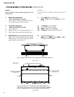
18.
Main Unit
(Time required: About 3 minutes)
18-1
Spread a soft cloth like a blanket on the floor where
the main unit is to be placed in advance.
18-2
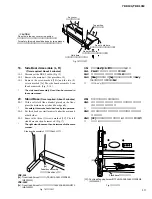
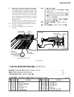
Disconnect the PK-LF cable. (Fig. 13)
18-3
Remove the four (4) screws marked [5c]. (Fig. 14)
18-4
Move the main unit backward, lift it and place it on
the cloth gently. (Fig. 15)
*
For safety, this work should be done by two persons.
18.
メインユニット
(所要時間:約3分)
18-1
あらかじめ、
メインユニットを置く場所に毛布など
の柔らかい布を敷いておきます。
18-2
PK-LFケーブルを外します。
(図13)
18-3
[5c]のネジ4本を外します。
(図14)
18-4
メインユニットを後方へずらした後、
持ち上げて布
の上に静かに置きます。
(図15)
※
安全のために、かならず二人で作業してください。
Fig. 14
(図14)
Fig. 13
(図13)
[5c]: Bind Head Screw (小ネジ+BIND) 6.0X16 MFZN2B3
(WE969400)
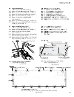
16.
Front rail Assembly
(Time required: About 12 minutes)
16-1
Remove the top board assembly. (See procedure 2)
16-2
Remove the key cover assembly. (See procedure 6)
16-3
Remove the stopper rail assembly. (See procedure 7)
16-4
Remove the rack L and R. (See procedure 8)
16-5
Remove the end block assembly L and R.
(See procedure 9)
16-6
Remove the keyboard assembly. (See procedure 10)
16-7
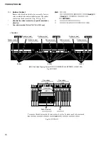
Remove the two (2) screws marked [S02B] each from
both sides of the assembly. (Fig. 11)
16-8
Remove the fourteen (14) screws marked [S01D]. The
front rail assembly can then be removed. (Fig. 12)
16.
口棒Ass y
(所要時間:約12分)
16-1
屋根Ass yを外します。
(2項参照)
16-2
スライド蓋Ass yを外します。
(6項参照)
16-3
鍵盤押えAss yを外します。
(7項参照)
16-4
ラック
(L・R)
を外します。
(8項参照)
16-5
拍子木Ass y (L・R)を外します。
(9項参照)
16-6
GHL (GHS) 鍵盤Ass yを外します。
(10項参照)
16-7
[S02B]のネジを左右2本ずつ外します。
(図11)
16-8
[S01D]のネジ14本を外し、
口棒Ass yを外します。
(図12)
PEDAL
PK-LF cable
(PK-LFケーブル)
17.
Arm Assembly (L, R)
(Time required: About 15 minutes)
17-1
Remove the top board assembly. (See procedure 2)
17-2
Remove the key cover assembly. (See procedure 6)
17-3
Remove the stopper rail assembly. (See procedure 7)
17-4
Remove the rack L and R. (See procedure 8)
17-5
Remove the end block assembly L and R.
(See procedure 9)
17-6
Remove the keyboard assembly. (See procedure 10)
17-7
Remove the three (3) screws marked [S02A] and the
tow (2) screws marked [S02B]. (Fig. 11)
17-8
Remove the four (4) screws marked [S01E]. The arm
assembly L can then be removed. (Fig. 12)
*
The arm assembly R can then be removed in the same
manner.
17.
腕木Ass y (L・R)
(所要時間:約15分)
17-1
屋根Ass yを外します。
(2項参照)
17-2
スライド蓋Ass yを外します。
(6項参照)
17-3
鍵盤押えAss yを外します。
(7項参照)
17-4
ラック
(L・R)
を外します。
(8項参照)
17-5
拍子木Ass y (L・R)を外します。
(9項参照)
17-6
GHL (GHS) 鍵盤Ass yを外します。
(10項参照)
17-7
[S02A]のネジ3本と、
[S02B]のネジ2本を外します。
(図11)
17-8
[S01E]のネジ4本を外し、
腕木Ass y Lを外します。
(図12)
※
腕木Ass y Rも同様に外すことができます。
[5c]


