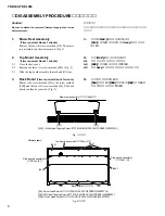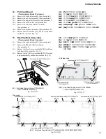
YDP-131/YDP-131C
8
6.
Key Cover Assembly
(Time required: About 2 minutes)
6-1
Close the key cover.
6-2
Remove the top board assembly. (See procedure 2)
6-3
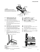
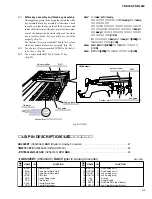
Lift the rear key cover assembly. (Fig. 5)
6-4
Lean slightly the key cover assembly so that the guide
pin can be removed from the guide rail. (Fig. 5-1)
*
When removing, be sure not to make scratches on the
side cover.
*
When reinstalling the key cover assembly, apply a
masking shield tape around the guide rail to prevent
from making scratches on the assembly.
6
スライド蓋Ass y
(所要時間:約2分)
6-1
スライド蓋を閉じます。
6-2
屋根Ass yを外します。
(2項参照)
6-3
スライド蓋後部を上に持ち上げます。
(図5)
6-4
スライド蓋Ass yを少し斜めにして、
ガイドピンをガ
イドレールから外します。
(図5-1)
※
腕木に傷をつけないように注意して取り外します。
※
組み付けのときには、ガイドレールの周囲にマスキング
テープを張り、傷がつかないようにします。
Fig. 5
(図5)
Fig. 5-1
(図5-1)
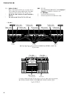
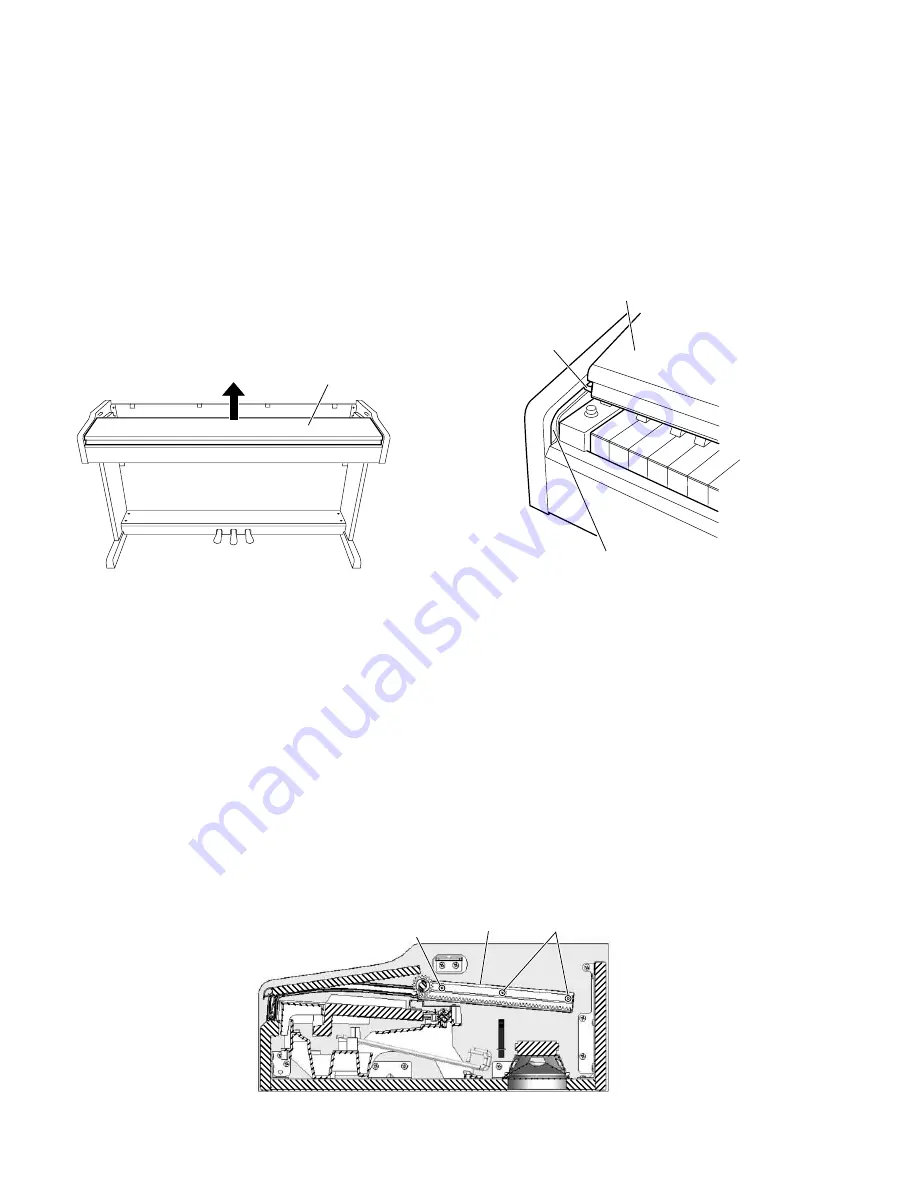
Fig. 6
(図6)
8.
Rack (L, R)
(Time required: About 3 minutes each)
8-1
Remove the top board assembly. (See procedure 2)
8-2
Remove the key cover assembly. (See procedure 6)
8-3
Remove the three (3) screws marked [S09]. The rack
L can then be removed. (Fig. 6)
*
The left and right rack can then be removed in the same
manner.
8.
ラック
(L・R)
(所要時間:各約3分)
8-1
屋根Ass yを外します。
(2項参照)
8-2
スライド蓋Ass yを外します。
(6項参照)
8-3
[S09]のネジ3本を外し、
ラック (L)を外します。
(図6)
※
ラック (R)も同様に外すことができます。
<Left side view>
Key cover assembly
(スライド蓋Ass'y)
Guide pin
(ガイドピン)
Guide rail
(ガイドレール)
Rack L
(ラック(L))
[S09]
[S09]
[S09]: Bind Head Tapping Screw-1 (TP#1+BIND) 3.5X20 MFZN2W3 (WE971500)
Key cover assembly
(スライド蓋Ass'y)
7.
Stopper Rail Assembly
(Time required: About 3 minutes)
7-1
Remove the top board assembly. (See procedure 2)
7-2
Remove the key cover assembly. (See procedure 6)
7-3
Remove the five (5) screws marked [S03C] . The
stopper rail assembly can then be removed. (Fig. 3)
7.
鍵盤押えAss y
(所要時間:約3分)
7-1
屋根Ass yを外します。
(2項参照)
7-2
スライド蓋Ass yを外します。
(6項参照)
7-3
[S03C]のネジ5本を外し、鍵盤押えAss yを外しま
す。
(図3)


