INSTALLING THE INCLUDED PARTS
– 6 –
7
9
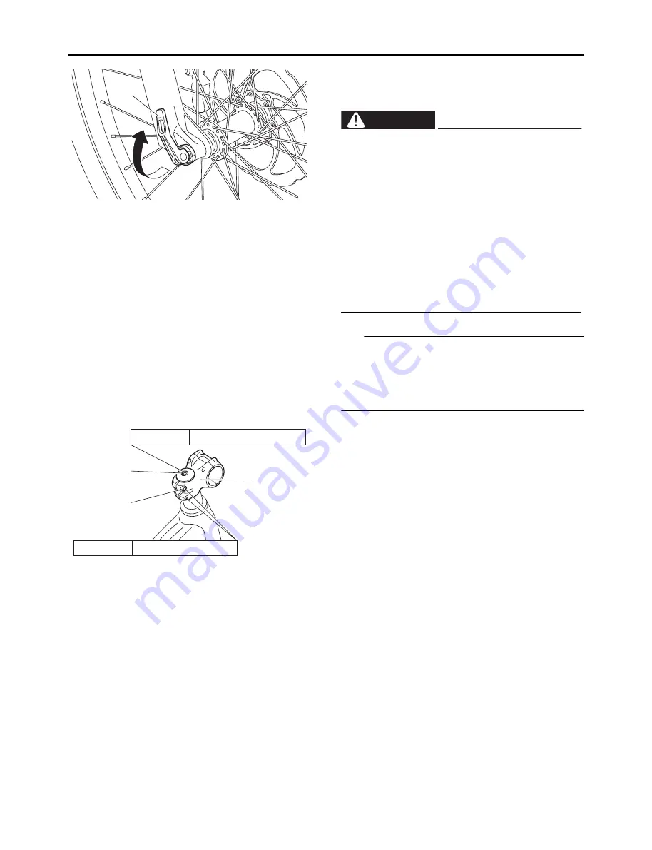
Free the lever
d
.
Determine the position to secure the lever
d
and fasten it at “CLOSE”.
TIP
If the lever
d
of the front axle
2
is too hard and
cannot be lowered, or if it is too loose and cannot
be lowered for it to be locked, turn the lever
d
again to loosen or tighten it, adjusting so that it can
be fastened securely.
2. Installing the handlebar stem
Position the handlebar stem
a
in a straight line
with the front wheel.
Tighten the bolts
b
and
c
, in that order, to the
specified torques.
d
8
Position the lever when it cannot touch
obstacles while the bicycle is moving. If not,
the lever could be unlocked unexpectedly,
causing the front wheel to come off, result-
ing in an accident with severe injury or
death.
8
Fasten the lever
d
at position where the tip
does not touch other parts when the lever
d
is lowered.
8
Fasten the lever
d
facing backward from
the direction of travel in such a way that it
cannot easily touch obstacles that might be
encountered while riding.
WARNING
b
a
c
Tightening tor
qu
e 8 N·m (0.8 kgf·m, 5.9 l
b
·ft)
Tightening tor
qu
e 2.5 N·m (0.25 kgf·m, 1.8 l
b
·ft)


