background image

– 37 –

CHAS

REAR BRAKE

EBS00410

REAR BRAKE

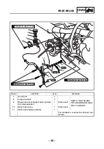
REAR BRAKE MASTER CYLINDER

T


R

.

.

7 Nm (0.7 m


 kg, 5.1 ft 

 Ib)

T


R

.

.

23 Nm (2.3 m 


kg, 17 ft


Ib)

T


R

.

.

27 Nm (2.7 m 


kg, 19 ft


Ib)

New

New

New

6

3

1

2

11

10

9

7

8

8

5

4

Order

Job/Part

Q’ty

Remarks

Removing the rear brake master cyl-
inder

Remove the parts in the order listed.

Right foot protector

Refer to “FOOT PROTECTORS, 
ENGINE SKID PLATE, AND FRONT 
BUMPER”. (Manual No.: 3GD-AE7)

Brake fluid

Drain.

1

Brake fluid reservoir cover

1

2

Brake fluid reservoir cap

1

3

Brake fluid reservoir diaphragm holder

1

4

Brake fluid reservoir diaphragm

1

5

Brake fluid reservoir

1

6

Brake fluid reservoir hose

1

Summary of Contents for YFM350R-W

Page 1: ...YFM350R W N0A1 AE1 SUPPLEMENTARY SERVICE MANUAL ...

Page 2: ...y Service Manual together with the following manual YFM350X J 97 SERVICE MANUAL 3GD AE5 YFM350X P 2002 SUPPLEMENTARY SERVICE MANUAL 3GD AE6 YFM350S SUPPLEMENTARY SERVICE MANUAL 3GD AE7 YFM350R W SUPPLEMENTARY SERVICE MANUAL 2005 by MBK Industrie First edition April 2005 All rights reserved Any reproduction or unauthorized use without the written permission of MBK Industrie is expressly prohibited ...

Page 3: ...and sig nificant changes in specifications or procedures will be forwarded to all authorized Yamaha dealers and will appear in future editions of this manual where applicable NOTE _ Designs and specifications are subject to change without notice EBS00003 IMPORTANT INFORMATION Particularly important information is distinguished in this manual by the following notations The Safety Alert Symbol means...

Page 4: ...parts and clarify procedure steps there are exploded diagrams at the start of each removal and disassembly section 1 An easy to see exploded diagram 4 is provided for removal and disassembly jobs 2 Numbers 5 are given in the order of the jobs in the exploded diagram A number that is enclosed by a circle indicates a disassembly step 3 An explanation of jobs and notes is presented in an easy to read...

Page 5: ...arance D Engine speed E Ω V A Illustrated symbols F to L in the exploded diagrams indicate the types of lubricants and lubrication points F Apply engine oil G Apply gear oil H Apply molybdenum disulfide oil I Apply wheel bearing grease J Apply lightweight lithium soap base grease K Apply molybdenum disulfide grease L Apply silicon grease Illustrated symbols M to N in the exploded diagrams indicate...

Page 6: ... BRAKE SYSTEM 27 ADJUSTING THE DRIVE CHAIN SLACK 29 ELECTRICAL 31 ADJUSTING THE HEADLIGHT BEAM 31 REPLACING THE HEADLIGHT BULB 31 CHASSIS 34 REAR WHEELS AND REAR AXLE HUB 34 INSTALLING THE SPEED SENSOR 36 REAR BRAKE 37 REAR BRAKE MASTER CYLINDER 37 INSTALLING THE REAR BRAKE MASTER CYLINDER 39 BRAKE EQUALIZER 40 BRAKE EQUALIZER 40 DISASSEMBLING THE BRAKE EQUALIZER 42 CHECKING THE BRAKE EQUALIZER 42...

Page 7: ...TRICAL 51 ELECTRICAL COMPONENTS 51 LIGHTING SYSTEM 53 CIRCUIT DIAGRAM 53 CHECKING THE LIGHTING SYSTEM 54 SIGNALING SYSTEM 57 CIRCUIT DIAGRAM 57 CHECKING THE SIGNALING SYSTEM 59 YFM350R W 2006 WIRING DIAGRAM ...

Page 8: ...GEN INFO EBS00009 GENERAL INFORMATION MACHINE IDENTIFICATION EBS00010 VEHICLE IDENTIFICATION NUMBER The vehicle identification number 1 is stamped into the right side of the frame 1 MACHINE IDENTIFICATION ...

Page 9: ...pe Dual disc brake front and single disc brake rear system Front and rear unified operation Right foot operation Headlight type HS1 Halogen Bulb wattage quantity Headlight 12 V 35 W 35 W 1 Auxiliary light 12 V 5 W 1 Tail brake light 12 V 5 W 21 W 1 License plate light 12 V 5 W 1 Front turn signal light 12 V 10 W 2 Rear turn signal light 12 V 10 W 2 Meter lighting EL electro luminescent lighting Ne...

Page 10: ...et P J 22 5 Pilot air jet P A J 1 65 P A J 2 165 Pilot outlet P O 1 Bypass 1 B P 1 0 8 Bypass 2 B P 2 0 8 Bypass 3 B P 3 0 8 Pilot screw turns out P S 2 1 4 Valve seat V S 2 5 Starter jet G S 70 Throttle valve size Th V 105 Fuel level F L 4 5 mm 0 16 0 20 in Above the float chamber mating surface Float height 13 0 mm 0 51 in Engine idling speed 1 450 1 550 r min Intake vacuum 33 3 kPa 250 mmHg 9 8...

Page 11: ...ket and handlebar M6 7 0 7 5 1 LT Left rearview mirror bracket and handlebar M6 7 0 7 5 1 Steering lock assembly front shock absorber and frame M10 48 4 8 35 Steering lock assembly bracket and steering lock assembly M8 28 2 8 20 Steering lock stopper and steering lock stopper bracket M8 28 2 8 20 Brake equalizer and steering lock assembly bracket M6 13 1 3 9 4 Brake hose brake equalizer to brake h...

Page 12: ... F Turn signal relay Relay type Full transistor Model manufacturer FE218BH DENSO Self cancelling device built in No Turn signal blinking frequency 75 95 cycles min Wattage 10 W 2 3 4 W Hazard light wattage 10 W 4 Circuit breaker Type Fuse Amperage for individual circuit Main fuse including headlight and brake light 15 A 1 Ancillary fuse turn signal horn speedome ter auxiliary light license plate l...

Page 13: ...Handlebar switch lead 0 Meter assembly lead È Fasten the clutch switch lead and handlebar switch lead with plastic bands É Fasten the engine stop switch lead and front brake light switch lead with plastic bands Ê 53 54 mm 2 09 2 13 in Ë 88 89 mm 3 46 3 50 in Ì Route the meter assembly lead along the han dlebar and then pass it to the front of the lower section of the handlebar 12 3 8 6 4 5 0 È É 7...

Page 14: ...0 Handlebar switch lead A Neutral reverse indicator light lead B Wire harness C Front turn signal light lead left D Front turn signal light lead right E Rectifier regulator lead È Pass the clutch switch lead handlebar switch lead neutral reverse indicator light lead front brake light switch lead starter cable and engine stop switch lead through the guide È É Ê Ë 1 E D C 2 3 4 5 6 7 8 9 0 A B 3 4 8...

Page 15: ...al light lead right horn lead headlight lead and front turn signal light lead left with a plastic locking tie Ë Fasten the handlebar switch lead neutral reverse indicator light lead clutch switch lead starter cable front brake light switch lead and engine stop switch lead with a plastic locking tie È É Ê Ë 1 E D C 2 3 4 5 6 7 8 9 0 A B 3 4 8 9 A 0 A A A A ...

Page 16: ...lead 7 Starter cable 8 Wire harness 9 Starter motor lead 0 Brake hose rear brake master cylinder to brake equalizer A Clutch cable B Parking brake cable C Brake hose brake hose joint to front brake cali per D Brake hose joint E Frame F Speed sensor lead G Sub wire harness B B C C A D A D C C B B Ì Í 0 4 3 D E 7 9 8 E F Î É È Ë Ê 0 3 4 9 8 7 6 5 4 3 2 1 C B A 0 G F G 8 7 9 ...

Page 17: ...25 Ë Route the headlight lead so that it does not con tact the front panel Ì Fasten the wire harness starter motor lead and starter cable with a plastic band Face the end of the plastic band down Í Fasten the speed sensor lead sub wire har ness wire harness starter cable and starter motor lead with a plastic locking tie Î 90 B B C C A D A D C C B B Ì Í 0 4 3 D E 7 9 8 E F Î É È Ë Ê 0 3 4 9 8 7 6 5...

Page 18: ...verflow hose B A C magneto lead C Neutral switch lead D Brake hose rear brake master cylinder to brake equalizer E Parking brake cable F Frame G Sub wire harness H Starter motor lead I Starting circuit cut off relay J C D I unit K Starter relay L Positive battery lead E E F F A A C C E E B B D D G G F F G G A A B C D D C B È Ê Ê Ì Ë É Í Î 1 F 8 H H 8 1 1 2 3 4 5 E D C B A 0 9 8 7 6 G H L K J 0 I 5...

Page 19: ... starter cable Ê Fasten the wire harness starter motor lead speed sensor lead and sub wire harness with a plastic locking tie Ë Fasten the wire harness and starter motor lead with a plastic band Face the end of the plastic band inward Ì Fasten the sub wire harness with a plastic lock ing tie Í Connect the sub wire harness to the wire har ness Î Connect the tail brake light lead to the wire har nes...

Page 20: ... hose brake equalizer to brake hose joint 9 Front turn signal light lead right 0 Horn lead A Brake hose brake hose joint to front brake cali per B Spark plug lead C Starter motor lead D Headlight lead not used È Fasten the headlight lead not used with a plas tic locking tie Also fasten the wire harness with a plastic locking tie in the same way on the left side of the vehicle A A A A È D 1 2 3 4 3...

Page 21: ... reservoir hose 4 Rear brake light switch lead 5 Brake hose rear brake master cylinder to brake equalizer 6 Speed sensor lead 7 Frame È Fasten the rear brake light switch lead and speed sensor lead with the plastic band C C D D B A A B C C D D È È 1 5 7 6 7 4 6 4 1 2 6 3 4 5 4 ...

Page 22: ...ht lead right 5 Rectifier regulator lead 6 Main switch lead 7 Spark plug lead 8 Drive select lever switch lead 9 Starter motor lead 0 Wire harness A Sub wire harness B Throttle cable C Ignition coil lead D Ground lead E Frame B B A A C C B B A A C C 1 3 4 D C B 5 E 6 7 8 3 1 2 0 4 E 4 A 0 9 È Ê É E 3 2 1 Ë Ì 2 2 ...

Page 23: ... signal light lead right with a plastic locking tie Ë Fasten the horn lead headlight lead and front turn signal light lead left with a plastic locking tie Ì Fasten the front turn signal light lead left head light lead front turn signal light lead right horn lead and wire harness with a plastic locking tie B B A A C C B B A A C C 1 3 4 D C B 5 E 6 7 8 3 1 2 0 4 E 4 A 0 9 È Ê É E 3 2 1 Ë Ì 2 2 ...

Page 24: ...signal light lead right 8 License plate light lead 9 Rear turn signal light lead left 0 Tail brake light lead A Negative battery lead B Starting circuit cut off relay C Starter motor lead D Sub wire harness E Wire harness È Make sure that the lead connections are posi tioned in the area shown in the illustration É Fasten the tail brake light lead with a plastic locking tie C E D C B A É 1 2 3 4 5 ...

Page 25: ...d right È 35 45 mm 1 38 1 77 in É 15 25 mm 0 59 0 98 in Ê Fasten the license plate light lead with a plastic clamp Ë Fasten the rear turn signal light lead with a plas tic clamp Ì 15 mm 0 59 in Í Fasten the rear turn signal light lead with the plastic locking tie A A A A B B 2 1 1 2 3 13 13 A A B B È È Ë Ì Ì Í Ê É ...

Page 26: ...2 Parking brake cable 3 Speed sensor lead È Fasten the parking brake cable and speed sen sor lead with a plastic locking tie É Fasten the speed sensor lead at the white mark on the lead with a plastic locking tie A A A A 1 2 3 2 3 2 1 3 È É È ...

Page 27: ...d be followed ITEM ROUTINE Whichever comes first INITIAL EVERY month 1 3 6 6 12 km mi 320 200 1 200 750 2 400 1 500 2 400 1 500 4 800 3 000 hours 20 75 150 150 300 Valves Check valve clearance Adjust if necessary Spark plug Check condition Adjust gap and clean Replace if necessary Air filter element Clean Replace if necessary Every 20 40 hours More often in wet or dusty areas Carburetor Check star...

Page 28: ...eals and O ring every two years Replace the brake hoses every four years or if cracked or damaged Steering system Check operation Repair if damaged Check toe in Adjust if necessary Front and rear suspension Check operation Correct if necessary Upper and lower arm pivot and steering shaft Lubricate every 6 months with lithium soap based grease Rear arm pivot Lubricate every 6 months with lithium so...

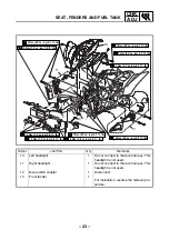
Page 29: ...13 12 3 7 6 5 4 1 9 2 8 Order Job Part Q ty Remarks Removing the headlights and front fender Remove the parts in the order listed Seat side covers left and right front panel Refer to SEAT SIDE COVERS AND FRONT PANEL Manual No 3GD AE7 1 Headlight coupler 1 Disconnect 2 Auxiliary light connector 1 Disconnect 3 Headlight assembly 1 4 Front turn signal light coupler left 1 Disconnect 5 Front turn sign...

Page 30: ... kg 5 1 ft Ib T R 6 Nm 0 6 m kg 4 3 ft Ib T R 13 Nm 1 3 m kg 9 4 ft Ib T R 13 Nm 1 3 m kg 9 4 ft Ib 10 11 13 12 3 7 6 5 4 1 9 2 8 Order Job Part Q ty Remarks 10 Left headlight 1 Do not connect to the wire harness This headlight is not used 11 Right headlight 1 Do not connect to the wire harness This headlight is not used 12 Main switch coupler 1 Disconnect 13 Front fender 1 For installation revers...

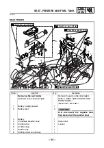
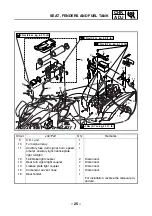
Page 31: ...ty Remarks Removing the rear fender Remove the parts in the order listed Seat side covers left and right Refer to SEAT SIDE COVERS AND FRONT PANEL Manual No 3GD AE7 1 Battery holding bracket 1 2 Battery lead 2 CAUTION _ First disconnect the negative lead then disconnect the positive lead 3 Battery 1 4 Crankcase breather hose 1 Disconnect 5 Clamp screw 1 Loosen 6 Air filter case 1 7 Starter relay 1...

Page 32: ...rder Job Part Q ty Remarks 9 C D I unit 1 10 Turn signal relay 1 11 Ancillary fuse turn signal horn speed ometer auxiliary light license plate light taillight 1 12 Tail brake light coupler 2 Disconnect 13 Rear turn signal light coupler 2 Disconnect 14 License plate light coupler 1 Disconnect 15 Carburetor air vent hose 1 Disconnect 16 Rear fender 1 For installation reverse the removal pro cedure ...

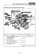
Page 33: ...ing the license plate light and rear turn signal lights Remove the parts in the order listed 1 License plate light coupler 1 Disconnect 2 License plate light 1 3 Rear turn signal light coupler left 1 Disconnect 4 Rear turn signal light left 1 5 Rear turn signal light coupler right 1 Disconnect 6 Rear turn signal light right 1 7 Rear reflector 2 For installation reverse the removal pro cedure ...

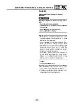
Page 34: ...erflow When bleeding the hydraulic brake system make sure there is always enough brake fluid before applying the brake Ignoring this precaution could allow air to enter the hydraulic brake system considerably length ening the bleeding procedure If bleeding is difficult it may be necessary to let the brake fluid settle for a few hours Repeat the bleeding procedure when the tiny bubbles in the hose ...

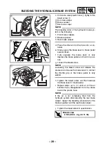
Page 35: ...ke pedal and hold it in posi tion g Loosen the bleed screw NOTE _ Loosening the bleed screw will release the pressure and cause the brake lever to contact the throttle grip or the brake pedal to fully extend h Tighten the bleed screw and then release the brake lever or brake pedal i Repeat steps e to h until all of the air bubbles have disappeared from the brake fluid in the plastic hose NOTE If t...

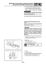
Page 36: ...n slack must be checked at the tightest point on the chain CAUTION A drive chain that is too tight will overload the engine and other vital parts and one that is too loose can skip and damage the swingarm or cause an accident Therefore keep the drive chain slack within the speci fied limits 1 Elevate the rear wheels by placing the suit able stand under the frame 2 Measure drive chain slack a Out o...

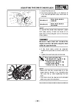
Page 37: ...ck within the specified limits e If the chain slack cannot be adjusted replace the sprockets and drive chain as a set f Tighten the axle hub bolts and locknuts NOTE Make sure that the curved edge d of the speed sensor bracket 5 is contacting the rear axle hub 6 when tightening the hub bolts The chain should be cleaned and lubricated after every use of the machine Direction a Drive chain slack is r...

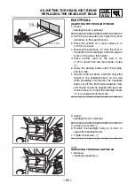
Page 38: ... 1 97 in lower than the mark made in step c e Apply the parking brake start the engine and let it idle f Switch on the low beam and then check the height of the headlight beam on the wall while straddling the vehicle The headlight beam cut off line the border between dark and bright should be aligned with the mark made in step d Adjust the headlight beam if it is not aligned with the mark H H 5 m ...

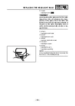
Page 39: ...oupler 1 4 Remove auxiliary light bulb socket 2 2 1 5 Remove headlight bulb cover 1 1 6 Detach headlight bulb holder 1 7 Remove headlight bulb 2 WARNING _ Keep flammable products and your hands away from the bulb while it is on since it will be hot Do not touch the bulb until it cools down 1 2 ...

Page 40: ...ous flux will be adversely affected If oil gets on the bulb thoroughly clean it with a cloth moistened with alcohol or lac quer thinner 9 Attach headlight bulb holder 10 Install headlight bulb cover 11 Install auxiliary light bulb socket 12 Connect headlight coupler 13 Install headlight body 1 headlight assembly NOTE Fit the headlight lead grommet 2 securely into the hole a in the headlight body N...

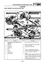
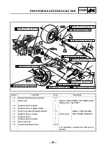
Page 41: ...4 4 4 4 3 New New LT LT LS LS T R 13 Nm 1 3 m kg 9 4 ft Ib Order Job Part Q ty Remarks Removing the rear wheels and rear axle hub Remove the parts in the order listed 1 Cotter pin 2 Refer to REAR WHEEL AND WHEEL HUB in chapter 6 Manual No 3GD AE5 2 Axle nut 2 3 Rear wheel 2 4 Wheel hub 2 5 Bolt 2 Refer to REMOVING THE REAR AXLE and INSTALLING THE REAR AXLE Manual No 3GD AE7 6 Nut 1 7 Locknut 2 8 A...

Page 42: ... 15 16 5 5 4 4 10 19 8 7 9 12 13 14 19 8 7 18 1 2 4 4 4 4 4 3 New New LT LT LS LS T R 13 Nm 1 3 m kg 9 4 ft Ib Order Job Part Q ty Remarks 10 Brake disc brake disc bracket 1 1 11 Rear axle 1 Refer to REMOVING THE REAR AXLE Manual No 3GD AE7 12 Speed sensor magnet 1 Refer to INSTALLING THE SPEED SENSOR 13 Speed sensor magnet holder 1 14 Driven sprocket sprocket bracket 1 1 15 Speed sensor coupler 1...

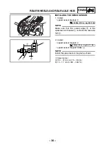
Page 43: ...curved edge a of the speed sensor bracket 1 contacts the rear axle hub 2 1 a 2 T R 120 Nm 12 0 m kg 85 ft lb 2 Install speed sensor magnet 1 speed sensor magnet holder 2 NOTE Install the speed sensor magnet as shown 3 Speed sensor a 19 0 21 0 mm 0 75 0 83 in b 1 5 1 7 mm 0 059 0 067 in 1 2 a b 3 T R 13 Nm 1 3 m kg 9 4 ft lb ...

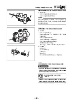
Page 44: ...Q ty Remarks Removing the rear brake master cyl inder Remove the parts in the order listed Right foot protector Refer to FOOT PROTECTORS ENGINE SKID PLATE AND FRONT BUMPER Manual No 3GD AE7 Brake fluid Drain 1 Brake fluid reservoir cover 1 2 Brake fluid reservoir cap 1 3 Brake fluid reservoir diaphragm holder 1 4 Brake fluid reservoir diaphragm 1 5 Brake fluid reservoir 1 6 Brake fluid reservoir h...

Page 45: ...3 1 2 11 10 9 7 8 8 5 4 Order Job Part Q ty Remarks 7 Union bolt 1 Refer to INSTALLING THE REAR BRAKE MAS TER CYLINDER 8 Copper washer 3 9 Brake hose rear brake master cylinder to brake equalizer 1 Disconnect 10 Rear brake hose 1 Disconnect 11 Rear brake master cylinder 1 For installation reverse the removal pro cedure ...

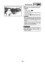
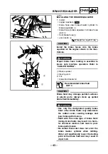
Page 46: ...ON _ When installing the rear brake hose onto the brake master cylinder make sure the brake pipe a touches the projection b as shown Install the brake hose rear brake master cylinder to brake equalizer at a 180 angle from the rear brake hose WARNING _ Proper brake hose routing is essential to insure safe machine operation Refer to CABLE ROUTING 180 1 2 3 a b New T R 27 Nm 2 7 m kg 19 ft lb ...

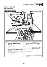
Page 47: ...g 4 3 ft Ib Order Job Part Q ty Remarks Removing the brake equalizer Remove the parts in the order listed Brake fluid Drain 1 Union bolt 3 Refer to INSTALLING THE BRAKE EQUAL IZER 2 Copper washer 6 3 Front brake hose 1 Disconnect 4 Brake hose brake equalizer to brake hose joint 1 5 Brake hose rear brake master cylinder to brake equalizer 1 Disconnect 6 Brake equalizer 1 For installation reverse th...

Page 48: ...rt Q ty Remarks Disassembling the brake equalizer Remove the parts in the order listed 1 Brake equalizer plug 1 Refer to DISASSEMBLING THE BRAKE EQUALIZER and ASSEM BLING THE BRAKE EQUALIZER 2 O ring 1 3 Spring 1 4 Piston seal 3 5 Piston 1 6 Bleed screw 1 7 Brake equalizer 1 For assembly reverse the disassembly procedure ...

Page 49: ...s Replace the brake equalizer brake equalizer body Cracks damage Replace brake fluid delivery passage brake equalizer body Blockage Blow out with compressed air 2 Check piston 1 piston seals 2 spring 3 O ring 4 Scratches wear damage Replace 1 1 2 3 4 EBS00416 ASSEMBLING THE BRAKE EQUALIZER WARNING _ All internal brake components should be cleaned and lubricated with new brake fluid only before ins...

Page 50: ...TION _ Brake fluid may damage painted surfaces or plastic parts Always clean up spilled brake fluid immediately WARNING _ Use only the designated quality brake fluid other brake fluids may deteriorate the rubber seals causing leakage and poor brake performance Refill with the same type of brake fluid mixing brake fluids may result in a harm ful chemical reaction and lead to poor brake performance ...

Page 51: ...ystem Refer to BLEEDING THE HYDRAULIC BRAKE SYSTEM 4 Check brake fluid level Brake fluid level is under the LOWER level line Add the recommended brake fluid to the proper level Refer to BRAKE FLUID LEVEL INSPEC TION in chapter 3 Manual No 3GD AE5 ...

Page 52: ...0 Order Job Part Q ty Remarks Removing the handlebar Remove the parts in the order listed 1 Stabilizer pad cover 1 2 Stabilizer pad 1 3 Meter assembly coupler 2 Disconnect 4 Meter assembly bracket 1 1 Refer to INSTALLING THE METER ASSEMBLY 5 Stabilizer bracket 1 4 6 Neutral reverse indicator light coupler 1 Disconnect 7 Handlebar cover 1 8 Left rearview mirror 1 9 Right rearview mirror 1 10 Front ...

Page 53: ... Part Q ty Remarks 13 Throttle lever assembly bracket 1 1 14 Clutch switch 1 15 Parking brake lever 1 16 Clutch lever bracket 1 1 Refer to INSTALLING THE LEFT REARVIEW MIRROR BRACKETS AND CLUTCH LEVER 17 Left rearview mirror bracket 2 18 Handlebar switch 1 19 Handlebar grip 2 20 Starter cable 1 Disconnect 21 Starter lever 1 22 Handlebar holder 2 Refer to STEERING SYSTEM in chap ter 6 Manual No 3GD...

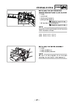
Page 54: ...et 3 NOTE Install the clutch lever bracket and left rearview mirror brackets as shown a 53 54 mm 2 09 2 13 in b 88 89 mm 3 46 3 50 in 1 2 3 a b T R 7 Nm 0 7 m kg 5 1 ft lb T R 7 Nm 0 7 m kg 5 1 ft lb INSTALLING THE METER ASSEMBLY 1 Install meter assembly 1 meter assembly bracket NOTE Be sure to fit the projection a on the meter assembly into the hole b in the stabilizer 2 1 2 a b ...

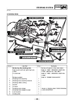
Page 55: ...LS 1 6 10 3 7 2 12 5 21 10 3 11 4 9 8 15 14 13 13 18 19 20 17 16 14 15 Order Job Part Q ty Remarks Removing the steering stem Remove the parts in the order listed Side covers left and right fuel tank shield Refer to SEAT FENDERS AND FUEL TANK Manual No 3GD AE7 Front fender Refer to SEAT FENDERS AND FUEL TANK Brake equalizer Refer to BRAKE EQUALIZER 1 Steering lock assembly 1 2 Steering lock assemb...

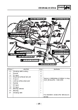
Page 56: ...Ib T R 48 Nm 4 8 m kg 35 ft Ib LS LS LS LS T R 23 Nm 2 3 m kg 17 ft Ib LS LS 1 6 10 3 7 2 12 5 21 10 3 11 4 9 8 15 14 13 13 18 19 20 17 16 14 15 Order Job Part Q ty Remarks 10 Steering stem bushing 2 11 Spacer 2 12 Oil seal 2 13 Right hand thread ball joint 2 Refer to STEERING SYSTEM in chap ter 6 Manual No 3GD AE5 14 Tie rod 2 15 Left hand thread ball joint 2 16 Spacer 1 17 Oil seal 1 18 Oil seal...

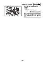
Page 57: ...LING THE STEERING LOCK STOPPER 1 Install steering lock stopper bracket 1 steering lock stopper 2 NOTE Make sure that the projection a on the steer ing lock stopper bracket contacts the pitman arm 3 1 2 3 a T R 28 Nm 2 8 m kg 20 ft lb ...

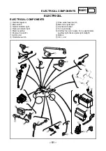
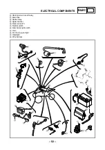
Page 58: ...ly 6 Engine stop switch 7 Ignition coil 8 Handlebar switch 9 Drive select lever switch 0 Rear turn signal light A License plate light B Turn signal relay C Ancillary fuse turn signal horn speedometer auxiliary light license plate light taillight D Battery E C D I unit 3 4 2 7 6 8 5 9 E D B 0 A 0 C F G H K J I L 1 O N M N P ELECTRICAL COMPONENTS ...

Page 59: ...g circuit cut off relay G Main fuse H Starter relay I Speed sensor J Reverse switch K Neutral switch L Rear brake light switch M Horn N Front turn signal light O Headlight P Wire harness 3 4 2 7 6 8 5 9 E D B 0 A 0 C F G H K J I L 1 O N M N P ...

Page 60: ...Br C C Br R R R A L B L W R B R W Br Br Br L Br G N BLACK Br W Br L Br L G B Dg P Y Br W Br G Br B G B Y Y B B B Dg B Dg B Ch B B Ch B B Dg Dg B B Ch B B Ch B Br L Y B Br L Br L Ch Dg Ch Dg Ch Y Dg Ch Br B Br L Br L Y B V Y W P Br B Br W Br L Br L Y B Br L Br W Br W L B R L B R B L R B B L R Y Y P V W Br Br R R WIRE HARNESS SUB WIRE HARNESS SUB WIRE HARNESS A WIRE HARNESS WIRE HARNESS B ENGINE STO...

Page 61: ...the light switch to or Measure the voltage DC 12 V of yellow 1 green 2 on the headlight coupler Is the voltage within specification This circuit is OK The wiring circuit from the main switch to the headlight cou pler is faulty and must be repaired DC 20V 2 É È 1 3 G Y B 1 Voltage Connect the pocket tester DC 20 V to the meter assembly coupler wire harness side as shown Positive tester probe yellow...

Page 62: ...ssem bly coupler is faulty and must be repaired Y B Br L Br L Dg Ch 1 2 Y V W P Y B Br 1 Auxiliary light bulb and socket Check the auxiliary light bulb and socket for continuity Are the auxiliary light bulb and socket OK Replace the auxiliary light bulb socket or both 2 Voltage Connect the pocket tester DC 20 V to the auxiliary light connector wire harness side as shown Positive tester probe brown...

Page 63: ...et or both 2 Voltage Connect the pocket tester DC 20 V to the license plate light coupler wire harness side as shown Positive tester probe brown blue 1 Negative tester probe black 2 Set the main switch to ON Measure the voltage DC 12 V of brown blue 1 on the license plate light coupler wire harness side Is the voltage within specification This circuit is OK The wiring circuit from the main switch ...

Page 64: ...Br Br G L W B G L R W R W Sb BLACK BLACK BLACK BLACK BLACK BLACK BLACK BLACK Y Br B B BLACK BLACK B Y B B Y B B B Br L B Y G B L Y Br B G L B GRAY B Y A Br Br Br C C Br R R R A L B L W R B R W Br Br Br L Br G N BLACK Br W Br L Br L G B Dg P Y Br W Br G Br B G B Y Y B B B Dg B Dg B Ch B B Ch B B Dg Dg B B Ch B B Ch B Br L Y B Br L Br L Ch Dg Ch Dg Ch Y Dg Ch Br B Br L Br L Y B V Y W P Br B Br W Br ...

Page 65: ...se switch I Ancillary fuse turn signal horn speedometer auxiliary light license plate light taillight J Rear brake light switch K Front brake light switch N Tail brake light O Turn signal relay Q Turn signal switch R Hazard switch T Horn switch V Horn Z Rear turn signal light right Rear turn signal light left Front turn signal light right Front turn signal light left _ Speed sensor b Multifunction...

Page 66: ...probe pink 1 Negative tester probe ground Set the main switch to ON Push the horn switch Measure the voltage DC 12 V of pink at the horn terminal Is the voltage within specification The wiring circuit from the main switch to the horn connector is faulty and must be repaired 3 Horn Disconnect the black lead at the horn ter minal Connect a jumper lead 1 to the horn ter minal and ground Set the main ...

Page 67: ...urn signal switch OK Replace the handle bar switch 3 Hazard switch Check the hazard switch for continuity Refer to CHECKING THE SWITCH Manual No 3GD AE6 Is the hazard switch OK Replace the handle bar switch 4 Voltage Connect the pocket tester DC 20 V to the turn signal relay coupler wire harness side as shown Positive tester probe brown blue 1 Negative tester probe ground Set the main switch to ON...

Page 68: ...nal light assembly right Ê Rear turn signal light assembly left Ë Rear turn signal light assembly right Ì Meter assembly Left turn signal light Positive tester probe chocolate 1 Negative tester probe ground Right turn signal light Positive tester probe dark green 2 Negative tester probe ground Br W Br L 1 Set the main switch to ON Set the turn signal switch to or Measure the voltage DC 12 V of the...

Page 69: ...ear wheels the voltage reading should cycle from 0 V to 4 6 V to 0 V to 4 6 V Does the voltage reading cycle correctly Replace the speed sensor L B R 2 1 L B R 0 4 6 È È Voltage V 1 cycle rotation Rotation of rear sprocket 2 Voltage Connect the pocket tester DC 20 V to the meter assembly coupler wire harness side as shown Positive tester probe brown blue 1 Negative tester probe black 2 Set the mai...

Page 70: ...urn signal relay P Handlebar switch Q Turn signal switch R Hazard switch S Light switch T Horn switch U Start switch V Horn W Headlight assembly X Auxiliary light Y Headlight Z Rear turn signal light right Rear turn signal light left Front turn signal light right Front turn signal light left Speed sensor a Meter assembly b Multifunction meter c Turn signal indicator light d High beam indicator lig...

Page 71: ......
Page 72: ...Br G L W B G L R W R W Sb BLACK BLACK BLACK BLACK BLACK BLACK BLACK BLACK Y Br B B BLACK BLACK B Y B B Y B B B Br L B Y G B L Y Br B G L B GRAY B Y A Br Br Br C C Br R R R A L B L W R B R W Br Br Br L Br G N BLACK Br W Br L Br L G B Dg P Y Br W Br G Br B G B Y Y B B B Dg B Dg B Ch B B Ch B B Dg Dg B B Ch B B Ch B Br L Y B Br L Br L Ch Dg Ch Dg Ch Y Dg Ch Br B Br L Br L Y B V Y W P Br B Br W Br L B...

Reviews: