–8–
B
1
2
3
A
7
FWD
A
B
3
20
2
2
1
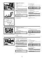
2. Front brake master cylinder
A: The handlebar holders should be
installed with the punched mark
forward.
CAUTION:
First tighten the bolts on the front
side, and then tighten the bolts on
the rear side.
B: Tighten the bolts to specified
torque.
3. Throttle housing
1. Handlebar
1
2
3
Handlebar
Handlebar holder
(upper)
Flange bolt
1
1
1
2
2
1
- S
2
- V
4
- V
2
- V
4
- V
d = 8 (0.31),
R
= 30 (1.18)
Tightening torque:
20 Nm (2.0 m • kg, 14 ft • lb)
1
2
3
Master cylinder
Bracket
Flange bolt
1
1
2
2
-
*
2
- V
2
- V
d = 6 (0.24),
R
= 22 (0.87)
A: Tighten the bolts to specified
torque.
Tightening torque:
7 Nm (0.7 m • kg, 5.1 ft • lb)
B: Check the brake lever for smooth
action.
1
2
3
Throttle housing
Bracket
Panhead screw with spring
washer
1
1
2
2
-
*
2
- V
2
- V
d = 5 (0.20),
R
= 20 (0.79)
A: Fit the throttle housing projection
to the brake master cylinder.
WARNING
Proper cable routing is essential to
assure safe machine operation.
Refer to “CABLE ROUTING”.
B: Tighten the screws in stages and
maintain an equal gap on each
side of the throttle housing
bracket.
C: Check the throttle lever for
smooth action.
WARNING
Proper hose routing is essential to
assure safe machine operation.
Refer to “CABLE ROUTING”.
B
1
2
3
C
A


