background image

– 14 –

CHAS

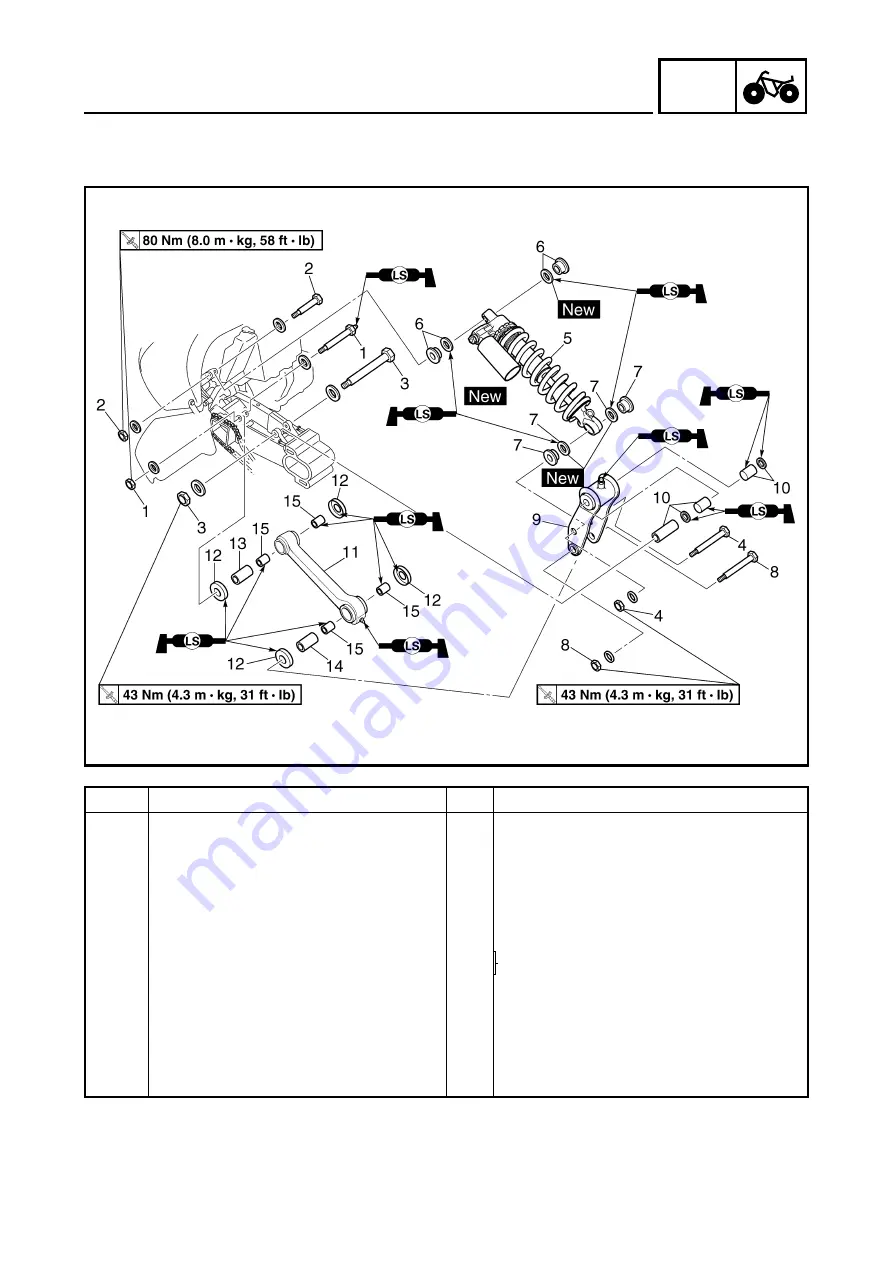
REAR SHOCK ABSORBER AND RELAY ARM

CHASSIS

REAR SHOCK ABSORBER AND RELAY ARM

Order

Job name/Part name

Q’ty

Remarks

Removing the rear shock absorber 
and relay arm

Remove the parts in the order below.

Muffler/exhaust pipe

Refer to “ENGINE REMOVAL” in CHAP-
TER 5. (Manual No.: 5LP2-AE1)

Rear wheels and hub

Refer to “REAR WHEELS, WHEEL AXLE
AND HUB”.

1

Self-locking nut/bolt

1/1

Refer to “REMOVING THE REAR 
SHOCK ABSORBER”.

2

Self-locking nut/bolt

1/1

3

Self-locking nut/bolt

1/1

4

Self-locking nut/bolt

1/1

5

Rear shock absorber

1

6

Collar/oil seal

2/2

7

Collar/oil seal

2/2

Summary of Contents for YFM660RP 5LP2-AE2 2002

Page 1: ...YFM660R P SUPPLEMENTARY SERVICEMANUAL 5LP2 AE2 2002 ...

Page 2: ......

Page 3: ...res it is necessary to use this Supplementary Service Manual together with the following manual YFM660R N 2001 SERVICE MANUAL 5LP2 AE1 YFM660R P 2002 SUPPLEMENTARY SERVICE MANUAL 2001 by Yamaha Motor Co Ltd First Edition August 2001 All rights reserved Any reproduction or unauthorized use without the written permission of Yamaha Motor Co Ltd is expressly prohibited ...

Page 4: ...fications and sig nificant changes in specifications or procedures will be forwarded to all authorized Yamaha dealers and will appear in future editions of this manual where applicable NOTE Designs and specifications are subject to change without notice IMPORTANT INFORMATION Particularly important information is distinguished in this manual by the following notations The Safety Alert Symbol means ...

Page 5: ...ntify parts and clarify procedure steps there are exploded diagrams at the start of each removal and disassembly section 1 An easy to see exploded diagram 4 is provided for removal and disassembly jobs 2 Numbers 5 are given in the order of the jobs in the exploded diagram A number that is enclosed by a circle indicates a disassembly step 3 An explanation of jobs and notes is presented in an easy t...

Page 6: ...Torque E Wear limit clearance F Engine speed G Ω V A Illustrated symbols H to N in the exploded diagrams indicate the types of lubricants and lubrication points H Apply engine oil I Apply gear oil J Apply molybdenum disulfide oil K Apply wheel bearing grease L Apply lightweight lithium soap base grease M Apply molybdenum disulfide grease N Apply silicon grease Illustrated symbols O to P in the exp...

Page 7: ...EAR SHOCK ABSORBER AND RELAY ARM 14 HANDLING THE REAR SHOCK ABSORBER AND GAS CYLINDER 16 DISPOSING OF A REAR SHOCK ABSORBER AND GAS CYLINDER 16 REMOVING THE REAR SHOCK ABSORBER 17 CHECKING THE REAR SHOCK ABSORBER 17 CHECKING THE RELAY ARM AND CONNECTING ARM 17 INSTALLING THE RELAY ARM AND CONNECTING ARM 18 INSTALLING THE REAR SHOCK ABSORBER 18 SWINGARM AND DRIVE CHAIN 19 ENGINE 21 ENGINE REMOVAL 2...

Page 8: ......

Page 9: ...tion ratio 71 34 2 088 Secondary reduction system Chain drive Secondary reduction ratio 40 13 3 076 Transmission type Constant mesh 5 speed forward 1 speed reverse Operation Left foot operation Gear ratio 1st gear 31 12 2 583 2nd gear 30 18 1 667 3rd gear 27 21 1 286 4th gear 22 21 1 047 5th gear 19 21 0 904 Reverse gear 33 25 25 18 1 833 GENERAL SPECIFICATIONS ...

Page 10: ... 042 mm 0 0004 0 0017 in Valve valve seat valve guide Valve clearance cold IN 0 10 0 15 mm 0 0039 0 0059 in EX 0 15 0 20 mm 0 0059 0 0079 in Valve dimensions A head diameter IN 29 9 30 1 mm 1 1772 1 1850 in EX 31 9 32 1 mm 1 2559 1 2638 in B face width IN 2 25 mm 0 0886 in EX 2 26 mm 0 0890 in C seat width IN 1 1 1 3 mm 0 0433 0 0512 in 1 6 mm 0 0630 in EX 0 9 1 1 mm 0 0354 0 0433 in 1 6 mm 0 0630...

Page 11: ... in Stem runout limit 0 01 mm 0 0004 in Valve seat width IN 1 1 1 3 mm 0 0433 0 0512 in 1 6 mm 0 0630 in EX 0 9 1 1 mm 0 0354 0 0433 in 1 6 mm 0 0630 in Piston Piston to cylinder clearance 0 05 0 07 mm 0 0020 0 0028 in 0 15 mm 0 0059 in Piston size D 99 945 99 995 mm 3 9348 3 9368 in Measuring point H 2 5 mm 0 10 in Piston off set 1 0 mm 0 04 in Off set direction Intake side Piston pin bore inside...

Page 12: ...13 mm 0 0051 in 2nd ring Type Taper Dimensions B T 1 2 4 0 mm 0 0472 0 1575 in End gap installed 0 30 0 45 mm 0 0118 0 0177 in 0 80 mm 0 0315 in Side clearance 0 03 0 07 mm 0 0012 0 0028 in 0 13 mm 0 0051 in Oil ring Dimensions B T 2 5 3 4 mm 0 0984 0 1339 in End gap installed 0 2 0 7 mm 0 0079 0 0276 in Side clearance 0 06 0 15 mm 0 0024 0 0059 in Item Standard Limit T B B T B T MAINTENANCE SPECI...

Page 13: ...e seat size V S 2 0 Starter jet G S 1 95 Starter jet G S 2 0 5 Throttle valve size Th V 80 Float height F H 13 mm 0 51 in Fuel level F L 3 4 mm 0 12 0 16 in Engine idle speed 1 450 1 550 r min Intake vacuum 32 0 33 3 kPa 240 250 mmHg 9 45 9 83 inHg Part to be tightened Part name Thread size Q ty Tightening torque Remarks Nm m kg ft lb Air filter case Bolt M6 2 9 0 9 6 5 Carburetor clamp Bolt M4 4 ...

Page 14: ...and frame M12 80 8 0 58 Relay arm and swingarm M10 43 4 3 31 Connecting arm and frame M12 80 8 0 58 Relay arm and rear shock absorber M10 43 4 3 31 Relay arm and connecting arm M10 43 4 3 31 Steering stem pitman arm and frame M14 180 18 130 Frame and bearing retainer M42 65 6 5 47 Rear brake fluid reservoir cover and bracket M6 11 1 1 8 0 Rear carrier bar and frame M8 33 3 3 24 Footrest guard brac...

Page 15: ...I unit 5 Wire harness 6 Rectifier regulator 7 Negative battery lead 8 AC magneto lead 9 Starter motor lead 0 Tail brake light lead A Rectifier regulator lead È Pass the negative battery lead between the wire harness and frame É 25 35 mm 0 98 1 38 in Ê 50 60 mm 1 97 2 36 in Ë 50 70 mm 1 97 2 76 in CABLE ROUTING ...

Page 16: ... Coolant reservoir breather hose 4 Negative battery lead 5 Coolant reservoir hose 6 Starter motor lead 7 Wire harness È Fasten the wire harness with the plastic clamp É Fasten the starter motor lead and starter relay lead with the plastic clamp CABLE ROUTING ...

Page 17: ...y Air filter element Clean Replace if necessary Every 20 40 hours More often in wet or dusty areas Carburetors Check starter choke operation Adjust engine idling speed and synchronization Crankcase breather system Check breather hose for cracks or damage Replace if necessary Exhaust system Check for leakage Tighten if necessary Replace gasket if necessary Fuel line Check fuel hose for cracks or da...

Page 18: ... When disassembling the master cylinder or caliper cylinder replace the brake fluid Normally check the brake fluid level and add fluid as required 2 On the inner parts of the master cylinder and caliper cylinder replace the oil seals every two years 3 Replace the brake hoses every four years or if cracked or damaged ...

Page 19: ...e spring installed changes 1 5 mm 0 06 in per turn of the adjuster CAUTION Never attempt to turn the adjusting ring beyond the maximum or minimum setting Tighten the locknut 1 NOTE Always tighten the locknut against the adjust ing ring then torque it to specification Direction a Spring preload is increased suspension is harder Direction b Spring preload is decreased suspension is softer Adjusting ...

Page 20: ...ion b Rebound damping force is decreased From the fully turned out position Standard 7 clicks in Minimum 1 clicks in Maximum 12 clicks in 3 Adjust Compression damping force Adjustment steps Turn the adjusting screw 1 in direction a or b Direction a Compression damping force is increased Direction b Compression damping force is decreased From the fully turned in position Standard 10 clicks out Mini...

Page 21: ... 13 CHK ADJ ADJUSTING THE REAR SHOCK ABSORBER CAUTION Do not force the adjuster past the minimum or maximum extent of adjustment The adjuster may be damaged ...

Page 22: ...arts in the order below Muffler exhaust pipe Refer to ENGINE REMOVAL in CHAP TER 5 Manual No 5LP2 AE1 Rear wheels and hub Refer to REAR WHEELS WHEEL AXLE AND HUB 1 Self locking nut bolt 1 1 Refer to REMOVING THE REAR SHOCK ABSORBER 2 Self locking nut bolt 1 1 3 Self locking nut bolt 1 1 4 Self locking nut bolt 1 1 5 Rear shock absorber 1 6 Collar oil seal 2 2 7 Collar oil seal 2 2 ...

Page 23: ...cking nut bolt 1 1 9 Relay arm 1 10 Spacer oil seal bushing 1 2 2 Refer to INSTALLING THE RELAY ARM AND CONNECTING ARM 11 Connecting arm 1 12 Dust cover 4 13 Spacer 1 14 Spacer 1 15 Bushing 4 Refer to INSTALLING THE RELAY ARM AND CONNECTING ARM For installation reverse the removal pro cedure ...

Page 24: ... or gas cylinder Do not subject the rear shock absorber or gas cylinder to an open flame or any other source of high heat High heat can cause an explosion due to excessive gas pressure Do not deform or damage the rear shock absorber or gas cylinder in any way If the rear shock absorber gas cylinder or both are damaged damping performance will suffer DISPOSING OF A REAR SHOCK ABSORBER AND GAS CYLIN...

Page 25: ...CK ABSORBER 1 Check Shock absorber Oil leaks Replace the rear shock absorber assembly Shock absorber rod Bends damage Replace the rear shock absorber assembly Spring Fatigue Replace the rear shock absorber assembly Move the spring up and down Gas cylinder Damage gas leaks Replace the rear shock absorber assembly CHECKING THE RELAY ARM AND CONNECTING ARM 1 Check Relay arm Connecting arm Damage wear...

Page 26: ...ng when installing Installed depth of bushing a 1 mm 0 04 in 2 Install Bushing 1 Oil seal 2 to relay arm NOTE Apply the lithium soap base grease on the bushing when installing Installed depth of bushing a 6 5 mm 0 26 in New INSTALLING THE REAR SHOCK ABSORBER 1 Install Connecting arm Relay arm Rear shock absorber NOTE When installing the rear shock absorber lift up the swingarm ...

Page 27: ...EAR WHEELS WHEEL AXLE AND HUB Rear shock absorber Refer to REAR SHOCK ABSORBER AND RELAY ARM Left footrest and left footrest guard bracket Refer to ENGINE REMOVAL in CHAP TER 5 Manual No 5LP2 AE1 1 Adjusting bolt nut 2 2 2 Swingarm skid plate 1 3 Drive chain guide 1 4 Pivot shaft nut washer 1 1 5 Pivot shaft 1 6 Swingarm 1 Refer to REMOVING THE SWINGARM 7 Drive sprocket cover 1 8 Drive chain guide...

Page 28: ...ING THE DRIVE SPROCKET 10 Lock washer 1 11 Drive sprocket 1 12 Drive chain 1 13 Collar 1 14 Spacer 1 15 Oil seal 1 16 Bearing 1 17 Dust cover oil seal washer 1 1 1 18 Spacer 1 19 Oil seal 2 20 Bushing 2 Refer to INSTALLING THE SWING ARM 21 Bearing 2 For installation reverse the removal pro cedure ...

Page 29: ...NOTE Do not fully tighten the bolts and nuts 2 Install Swingarm Pivot shaft nut 9 NOTE Do not fully tighten the pivot shaft nut 3 Tighten Engine bracket bolt upper 7 Pivot shaft nut 9 Engine mounting bolt upper nut 8 Engine mounting bolt middle nut 5 Engine mounting bolt lower nut 4 Engine bracket bolt lower 2 T R 33 Nm 3 3 m kg 24 ft lb T R 95 Nm 9 5 m kg 68 ft lb T R 40 Nm 4 0 m kg 29 ft lb T R ...

Page 30: ... in the order below Engine oil Drain Shift pedal link Disconnect 1 Oil pipe 1 1 Disconnect 2 AC magneto coupler 2 3 Starter idle gear cover gasket 1 1 4 Dowel pin 1 5 Starter idle gear 1 1 6 Starter idle gear 1 shaft 1 7 Bearing 1 8 AC magneto cover gasket 1 1 Refer to REMOVING INSTALLING THE AC MAGNETO ROTOR ...

Page 31: ...ad holder 1 11 Pickup coil 1 12 Stator assembly 1 13 Starter idle gear 2 1 14 Starter idle gear 2 shaft 1 15 AC magneto rotor 1 Refer to REMOVING INSTALLING THE AC MAGNETO ROTOR 16 Starter wheel gear 1 17 Woodruff key 1 18 Bush washer 1 1 For installation reverse the removal pro cedure ...

Page 32: ......

Page 33: ... 0 A B C D E F G H I J K L M N O T U P R R S Q 1 AC magneto 2 Rectifier regulator 3 Main switch 4 Battery 5 Fuse 6 Starter relay 7 Starter motor 8 Clutch switch 9 Park switch 0 CDI unit A Ignition coil B Spark plug C Speed sensor D Circuit breaker fan motor E Thermo switch 1 F Fan motor G Coolant temperature warning light H Reverse indicator light I Neutral indicator light J Neutral switch K Rever...

Reviews: