4 - 14
ENG
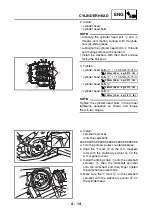
2. Install:
• cylinder head
• cylinder head bolts
NOTE:
• Lubricate the cylinder head bolt
1
and
2
threads and mating surface with molybde-
num disulfide grease.
• Lubricate the cylinder head bolts
3
threads
and mating surface with engine oil.
• Install the washers with their blunt surface
facing the bolt seat.
3. Tighten:
• cylinder head bolts
1
:
= 135 mm (5.31 in)
• cylinder head bolts
2
:
= 145 mm (5.71 in)
• cylinder head bolts
3
• cylinder head bolts
4
NOTE:
_
Tighten the cylinder head bolts in the proper
tightening sequence as shown and torque
them in two stages.
3
1
1
4
7
8
5
6
4
4
2
2
3
3
T
R
.
.
35 Nm (3.5 m · kg, 25 ft · lb)
T
R
.
.
35 Nm (3.5 m · kg, 25 ft · lb)
T
R
.
.
38 Nm (3.8 m · kg, 27 ft · lb)
T
R
.
.
10 Nm (1.0 m · kg, 7.2 ft · lb)
4. Install:
• camshaft sprocket
(onto the camshaft)
▼▼▼
▼
▼ ▼▼▼
▼
▼ ▼▼▼
▼
▼ ▼▼▼
▼
▼ ▼▼▼
▼
▼ ▼▼▼
▼
▼▼▼
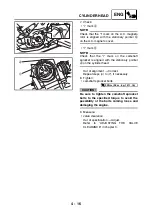
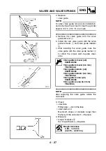
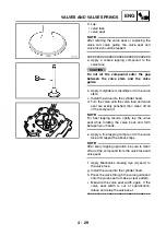
a. Turn the primary pulley counterclockwise.
b. Align the “I” mark
a
on the A.C. magneto
rotor with the stationary pointer
b
on the
A.C. magneto cover.
c. Install the timing chain
1
onto the camshaft
sprocket
2
, then the camshaft sprocket
onto the camshaft, and then finger tighten
the camshaft sprocket bolts.
d. Make sure the “I” mark
c
on the camshaft
sprocket with the stationary pointer
d
on
the cylinder head.
a
b
1
c
d
2
Summary of Contents for YFM700RV 2006
Page 1: ...YFM700RV SERVICE MANUAL 1S3 28197 E0 ...
Page 34: ...2 11 SPEC ENGINE SPECIFICATIONS Cylinder head tightening sequence 1 3 2 4 5 7 8 6 ...
Page 52: ...2 29 SPEC OIL FLOW DIAGRAMS 1 Oil delivery pipe 2 Oil filter 3 Oil pump 2 3 A A A A 2 1 ...
Page 55: ...2 32 SPEC OIL FLOW DIAGRAMS 1 Balancer 1 2 Crankshaft 2 1 ...
Page 408: ...YAMAHA MOTOR CO LTD 2500 SHINGAI IWATA SHIZUOKA JAPAN ...


