4 - 16
ENG
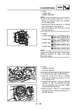
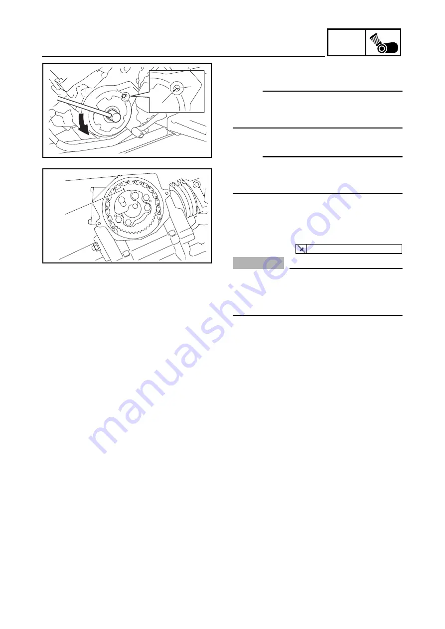
7. Check:
• “I” mark
a
NOTE:
Check that the “I” mark on the A.C. magneto
rotor is aligned with the stationary pointer
b
on the A.C. magneto cover.
• “I” mark
c
NOTE:
Check that the “I” mark on the camshaft
sprocket is aligned with the stationary pointer
d
on the cylinder head.
Out of alignment
→
Correct.
Repeat steps (4) to (7), if necessary.
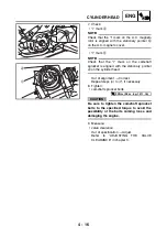
8. Tighten:
• camshaft sprocket bolts
CAUTION:
_
Be sure to tighten the camshaft sprocket
bolts to the specified torque to avoid the
possibility of the bolts coming loose and
damaging the engine.
9. Measure:
• valve clearance
Out of specification
→
Adjust.
Refer to “ADJUSTING THE VALVE
CLEARANCE” in chapter 3.
a
b
d
c
T
R
.
.
20 Nm (2.0 m · kg, 14 ft · lb)
Summary of Contents for YFM700RV 2006
Page 1: ...YFM700RV SERVICE MANUAL 1S3 28197 E0 ...
Page 34: ...2 11 SPEC ENGINE SPECIFICATIONS Cylinder head tightening sequence 1 3 2 4 5 7 8 6 ...
Page 52: ...2 29 SPEC OIL FLOW DIAGRAMS 1 Oil delivery pipe 2 Oil filter 3 Oil pump 2 3 A A A A 2 1 ...
Page 55: ...2 32 SPEC OIL FLOW DIAGRAMS 1 Balancer 1 2 Crankshaft 2 1 ...
Page 408: ...YAMAHA MOTOR CO LTD 2500 SHINGAI IWATA SHIZUOKA JAPAN ...


