4 - 56
ENG
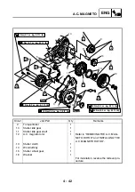
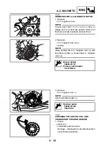
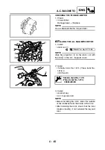
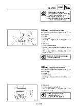
2. Tighten:
• balancer driven gear 2 nut
1
• primary drive gear nut
2
• balancer driven gear 1 nut
3
NOTE:
_
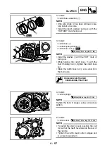
• Apply the engine oil to the balancer threads.
• Apply the molybdenum disulfide grease to
the crankshaft and nut
2
threads.
• Place an aluminum plate
4
between the
teeth of the balancer driven gear 2
5
and
balancer drive gear
6
, then tighten the nut
1
.
• Place an aluminum plate
7
between the
teeth of the balancer driven gear 2
5
and
balancer drive gear
6
, then tighten the nut
2
.
• Place an aluminum plate
8
between the
teeth of the balancer drive gear
6
and bal-
ancer driven gear 1
9
, then tighten the nut
3
.
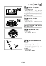
3. Bend the lock washer tabs along a flat side
of the nut.
5
6
2
9
3
7
8
4
1
T
R
.
.
60 Nm (6.0 m · kg, 43 ft · lb)
T
R
.
.
110 Nm (11.0 m · kg, 80 ft · lb)
T
R
.
.
60 Nm (6.0 m · kg, 43 ft · lb)
EBS00311
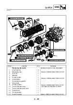
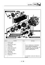
INSTALLING THE CLUTCH
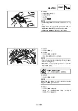
1. Install:
• clutch housing
1
NOTE:
_
• Make sure that the primary driven gear teeth
and primary drive gear teeth mesh correctly.
• Make sure that the oil pump drive gear teeth
and oil pump driven gear teeth mesh cor-
rectly.
1
Summary of Contents for YFM700RV 2006
Page 1: ...YFM700RV SERVICE MANUAL 1S3 28197 E0 ...
Page 34: ...2 11 SPEC ENGINE SPECIFICATIONS Cylinder head tightening sequence 1 3 2 4 5 7 8 6 ...
Page 52: ...2 29 SPEC OIL FLOW DIAGRAMS 1 Oil delivery pipe 2 Oil filter 3 Oil pump 2 3 A A A A 2 1 ...
Page 55: ...2 32 SPEC OIL FLOW DIAGRAMS 1 Balancer 1 2 Crankshaft 2 1 ...
Page 408: ...YAMAHA MOTOR CO LTD 2500 SHINGAI IWATA SHIZUOKA JAPAN ...

