4 - 85
ENG
EBS00356
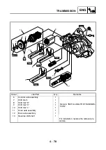
INSTALLING THE TRANSMISSION
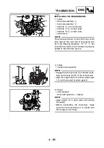
1. Install:
• drive axle assembly
1
• main axle assembly
2
• shift fork “L”
3
(to drive axle)
• shift fork “C”
4
(to main axle)
• shift fork “R”
5
(to drive axle)
• shift drum
6
NOTE:
_
The embossed marks on the shift forks should
face towards the right side of the engine and
be in the following sequence: “R”, “C”, “L”. Be
sure that the shift fork cam follower is properly
seated in the shift drum groove.
5
4
3
6
2
1
2. Install:
• counter axle assembly
NOTE:
_
• Engage the concave part
a
of the left crank-
case and convex part
b
of the counter axle.
• Align the edge height of reverse wheel gear
1
c
and main axle/1st pinion gear
d
.
a
b
c
d
3. Check:
• shift operation
Unsmooth operation
→
Repair.
NOTE:
_
• Apply engine oil to each gear and bearing
thoroughly.
• Before assembling the crankcase, make
sure that the transmission is in neutral and
that the gears turn freely.
Summary of Contents for YFM700RV 2006
Page 1: ...YFM700RV SERVICE MANUAL 1S3 28197 E0 ...
Page 34: ...2 11 SPEC ENGINE SPECIFICATIONS Cylinder head tightening sequence 1 3 2 4 5 7 8 6 ...
Page 52: ...2 29 SPEC OIL FLOW DIAGRAMS 1 Oil delivery pipe 2 Oil filter 3 Oil pump 2 3 A A A A 2 1 ...
Page 55: ...2 32 SPEC OIL FLOW DIAGRAMS 1 Balancer 1 2 Crankshaft 2 1 ...
Page 408: ...YAMAHA MOTOR CO LTD 2500 SHINGAI IWATA SHIZUOKA JAPAN ...


