2 - 34
SPEC
È
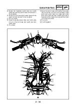
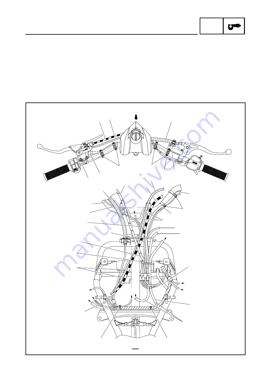
Fasten the handlebar switch lead and clutch
switch lead with the plastic bands at the bends in
the handlebar.
É
Fasten the front brake light switch lead with the
plastic band at the bend in the handlebar.
Ê
To main switch
Ë
Route the parking brake cable and clutch cable
in front of the front brake light switch and main
switch lead.
Ì
To radiator
Í
Route the coolant reservoir breather hose under
the wire harness and over the handlebar switch
lead, clutch switch lead, front brake light switch
lead, main switch lead and indicator light assem-
bly lead and then fasten the hose with the holder
on the fuel tank shield.
Î
To resistor
Ï
To left headlight
2
1
3
4
7
5
6
7
6
5
4
3
È
É
È
Ë
Ì
Í
Î
Ï
Ð
Ñ
Ó
Ô
Õ
Ö
×
Ø
Ù
Ú
Û
A
A
A
0
9
8
1
2
Ê
Ò
B
C
Summary of Contents for YFM700RV 2006
Page 1: ...YFM700RV SERVICE MANUAL 1S3 28197 E0 ...
Page 34: ...2 11 SPEC ENGINE SPECIFICATIONS Cylinder head tightening sequence 1 3 2 4 5 7 8 6 ...
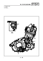
Page 52: ...2 29 SPEC OIL FLOW DIAGRAMS 1 Oil delivery pipe 2 Oil filter 3 Oil pump 2 3 A A A A 2 1 ...
Page 55: ...2 32 SPEC OIL FLOW DIAGRAMS 1 Balancer 1 2 Crankshaft 2 1 ...
Page 408: ...YAMAHA MOTOR CO LTD 2500 SHINGAI IWATA SHIZUOKA JAPAN ...


