4 - 57
ENG
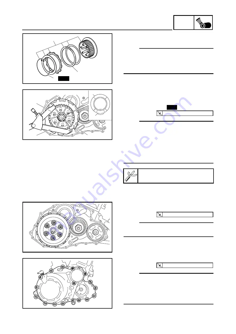
2. Install:
• clutch boss assembly
1
NOTE:
• If the wire circlip
2
has been removed, care-
fully install a new one.
• Install the clutch damper spring
3
with the
“OUTSIDE” mark facing out.
1
3
2
New
3. Install:
• clutch boss
1
• conical spring washer
2
• clutch boss nut
3
NOTE:
_
• Install the washer
2
with the “OUT” mark
a
facing out.
• While holding the clutch boss
1
with the
clutch holding tool
4
, tighten the clutch boss
nut.
• Stake the clutch boss nut
3
at a cutout
b
in
the main axle.
Universal clutch holder
90890-04086, YM-91042
OUT
3
1
4
b
2
a
New
T
R
.
.
95 Nm (9.5 m · kg, 68 ft · lb)
4. Install:
• clutch springs
NOTE:
_
Tighten the bolts in stages, using a crisscross
pattern.
T
R
.
.
8 Nm (0.8 m · kg, 5.8 ft · lb)
5. Install:
• clutch cover
NOTE:
_
• To install the clutch cover, position the pull
rod so that the teeth face towards the rear of
the vehicle.
• Tighten the clutch cover bolts in stages and
in a crisscross pattern.
T
R
.
.
10 Nm (1.0 m · kg, 7.2 ft · lb)
Summary of Contents for YFM700RV 2009
Page 1: ...YFM700RV SERVICE MANUAL 1S3 28197 E0 ...
Page 34: ...2 11 SPEC ENGINE SPECIFICATIONS Cylinder head tightening sequence 1 3 2 4 5 7 8 6 ...
Page 52: ...2 29 SPEC OIL FLOW DIAGRAMS 1 Oil delivery pipe 2 Oil filter 3 Oil pump 2 3 A A A A 2 1 ...
Page 55: ...2 32 SPEC OIL FLOW DIAGRAMS 1 Balancer 1 2 Crankshaft 2 1 ...
Page 408: ...YAMAHA MOTOR CO LTD 2500 SHINGAI IWATA SHIZUOKA JAPAN ...


