4 - 11
ENG
EBS00220
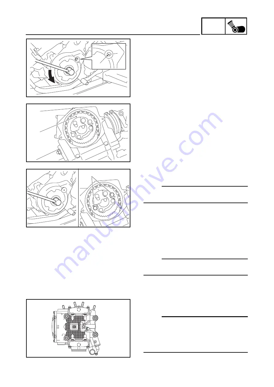
REMOVING THE CYLINDER HEAD
1. Align:
• “I” mark
a
on the A.C. magneto rotor
(with the stationary pointer
b
on the A.C.
magneto cover)
▼▼▼
▼
▼ ▼▼▼
▼
▼ ▼▼▼
▼
▼ ▼▼▼
▼
▼ ▼▼▼
▼
▼ ▼▼▼
▼
▼▼▼
a. Turn the crankshaft counterclockwise.
b. When the piston is at top dead center (TDC)
on the compression stroke, align the “I”
mark
c
on the camshaft sprocket with the
stationary pointer
d
on the cylinder head.
▲▲▲
▲
▲ ▲▲▲
▲
▲ ▲▲▲
▲
▲ ▲▲▲
▲
▲ ▲▲▲
▲
▲ ▲▲▲
▲
▲▲▲
a
b
d
c
2. Loosen:
• camshaft sprocket bolts
1
NOTE:
While holding the A.C. magneto rotor nut with
a wrench, loosen the bolt.
3. Loosen:
• timing chain tensioner cap bolt
4. Remove:
• timing chain tensioner
(along with the gasket)
• camshaft sprocket
• timing chain
NOTE:
_
To prevent the timing chain from falling into the
crankcase, fasten it with a wire.
1
5. Remove:
• cylinder head
NOTE:
_
• Loosen the bolts in the proper sequence as
shown.
• Loosen each bolt 1/2 of a turn at a time. After
all of the bolts are fully loosened, remove
them.
6
8
5
7
2
1
4
3
Summary of Contents for YFM700RV 2009
Page 1: ...YFM700RV SERVICE MANUAL 1S3 28197 E0 ...
Page 34: ...2 11 SPEC ENGINE SPECIFICATIONS Cylinder head tightening sequence 1 3 2 4 5 7 8 6 ...
Page 52: ...2 29 SPEC OIL FLOW DIAGRAMS 1 Oil delivery pipe 2 Oil filter 3 Oil pump 2 3 A A A A 2 1 ...
Page 55: ...2 32 SPEC OIL FLOW DIAGRAMS 1 Balancer 1 2 Crankshaft 2 1 ...
Page 408: ...YAMAHA MOTOR CO LTD 2500 SHINGAI IWATA SHIZUOKA JAPAN ...


