6 - 10
FI
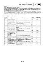
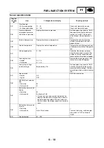
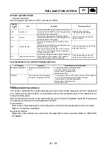
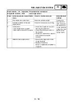
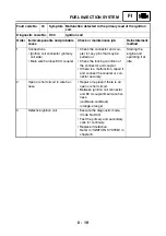
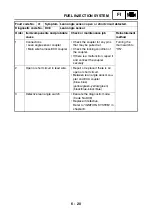
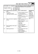
Sensor operation table
Diagnos-
tic code
No.
Item
FI diagnostic tool display
Checking method
D01
Throttle angle
• Fully closed position
15 ~ 20
Check with throttle fully closed.
• Fully opened position
95 ~ 100
Check with throttle fully open.
D03
Pressure difference
(atmospheric pressure
and intake air pressure)
Displays the intake air pressure.
Set the engine stop switch to “RUN”,
then operate the throttle while push-
ing the start switch. (If the display
value changes, the performance is
OK.)
D05
Intake air temperature
Displays the intake air temperature.
Compare the actually measured
intake air temperature with the FI
diagnostic tool.
D06
Coolant temperature
Displays the coolant temperature.
Compare the actually measured cool-
ant temperature with the FI diagnostic
tool.
D07
Vehicle speed pulse
0 ~ 999
Check that the number increases
when the rear wheel is rotated. The
number is cumulative and does not
reset each time the wheel is stopped.
D08
Lean angle sensor
Remove the lean angle sensor and
incline it more than 65 degrees.
• Upright
0.4 ~ 1.4
• Overturned
3.7 ~ 4.4
D09
Fuel system voltage
(battery voltage)
Approximately 12.0
Set the engine stop switch to “RUN”,
and then compare with the actually
measured battery voltage. (If the bat-
tery voltage is lower, perform recharg-
ing.)
D21
Neutral switch
Shift the transmission.
• Neutral
ON
• In gear
OFF
D60
EEPROM fault code dis-
play
—
• No history
00
• History exists
01
D61
Malfunction history code
display
—
• No history
00
• History exists
Fault codes 12-63
• (If more than one code number is detected, the
display alternates every two seconds to show all
the detected code numbers. When all code num-
bers are shown, the display repeats the same pro-
cess.)
D62
Malfunction history code
erasure
• No history
0
—
• History exists
Up to 15 fault codes
To erase the history, set the engine
stop switch to “OFF” and then to
“RUN”.
D70
Control number
00 ~ 255
—
Summary of Contents for YFM700RV 2009
Page 1: ...YFM700RV SERVICE MANUAL 1S3 28197 E0 ...
Page 34: ...2 11 SPEC ENGINE SPECIFICATIONS Cylinder head tightening sequence 1 3 2 4 5 7 8 6 ...
Page 52: ...2 29 SPEC OIL FLOW DIAGRAMS 1 Oil delivery pipe 2 Oil filter 3 Oil pump 2 3 A A A A 2 1 ...
Page 55: ...2 32 SPEC OIL FLOW DIAGRAMS 1 Balancer 1 2 Crankshaft 2 1 ...
Page 408: ...YAMAHA MOTOR CO LTD 2500 SHINGAI IWATA SHIZUOKA JAPAN ...

