6 - 11
FI
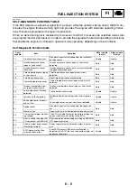
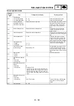
Actuator operation table
• Actuator operation
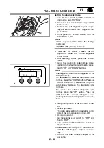
Set the engine stop switch to “OFF” and then to “RUN”.
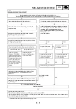
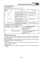
Communication error with the FI diagnostic tool
EAS00908
TROUBLESHOOTING DETAILS
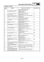
This section describes the countermeasures per fault code number displayed on the FI diagnostic
tool. Check and service the items or components that are the probable cause of the malfunction fol-
lowing the order given.
After the check and service of the malfunctioning part has been completed, reset the FI diagnostic
tool display according to the “Reinstatement method”.
Fault code No.:
Fault code number displayed on the FI diagnostic tool when the engine failed to work normally.
Refer to “Diagnostic code table”.
Diagnostic code No.:
Diagnostic code number to be used when the diagnostic mode is operated. Refer to “DIAGNOS-
TIC MODE”.
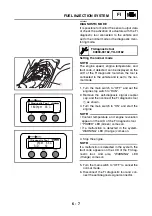
Diagnos-
tic code
No.
Item
Actuation
Checking method
D30
Ignition coil
Actuates the ignition coil for five times every second.
Illuminates the “WARNING” on the FI diagnostic tool
and engine trouble warning light.
Check the spark five times.
• Connect an ignition checker.
D36
Injector
Actuates the injector for five times every second.
Illuminates the “WARNING” on the FI diagnostic tool
and engine trouble warning light.
Check the operating sound of the
injector five times.
D50
Fuel pump relay
Actuates the fuel pump relay for five times every
second.
Illuminates the “WARNING” on the FI diagnostic tool
and engine trouble warning light.
(The engine trouble warning light is OFF when the
relay is ON, and the engine trouble warning light is
ON when the relay is OFF).
Check the operating sound of the fuel
pump relay five times.
D51
Radiator fan motor relay
Actuates the radiator fan motor relay for five cycles
of five seconds. (ON 2 seconds, OFF 3 seconds)
Illuminates the engine trouble warning light.
Check the operating sound of the
radiator fan motor relay five times.
LCD Display
Symptom
Probable cause of malfunction
Waiting for connection....
No signals are received from the
ECU.
• Improper connection in connecting lead.
• The main switch is OFF position.
• Malfunction in FI diagnostic tool.
• Malfunction in ECU.
ERROR 4
Commands from the FI diagnostic
tool are not accepted by the ECU.
• Turn the main switch to “OFF” once, and then set the FI diagnos-
tic tool to CO adjustment mode or diagnostic mode.
• Vehicle battery is insufficiently charged.
• Malfunction in FI diagnostic tool.
• Malfunction in ECU.
Summary of Contents for YFM700RV 2009
Page 1: ...YFM700RV SERVICE MANUAL 1S3 28197 E0 ...
Page 34: ...2 11 SPEC ENGINE SPECIFICATIONS Cylinder head tightening sequence 1 3 2 4 5 7 8 6 ...
Page 52: ...2 29 SPEC OIL FLOW DIAGRAMS 1 Oil delivery pipe 2 Oil filter 3 Oil pump 2 3 A A A A 2 1 ...
Page 55: ...2 32 SPEC OIL FLOW DIAGRAMS 1 Balancer 1 2 Crankshaft 2 1 ...
Page 408: ...YAMAHA MOTOR CO LTD 2500 SHINGAI IWATA SHIZUOKA JAPAN ...

