


1-3
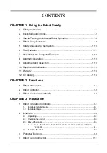
CHAPTER 1 Using the Robot Safely
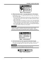
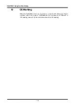
Moving parts can
pinch or crush.
Keep hands away
from robot arms.
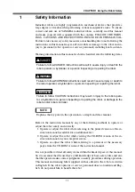
WARNING
■
Fig. 1-2 Warning label 2
(3) Follow the instructions on warning labels and in this manual.
Warning label 3 (Fig. 1-3) is affixed to the robot. See Fig. 2-2 for the loca-
tions of warning labels.
• Be sure to read the warning label and this manual carefully and make you
thoroughly understand the contents before attempting installation and op-
eration of the robot.
• Before starting the robot operation, even after you have read through this
manual, read again the corresponding procedures and cautions in this manual
as well as descriptions in this chapter (Chapter 1, "Using the Robot Safely").
• Never install, adjust, inspect or service the robot in any manner that does
not comply with the instructions in this manual.
WARNING
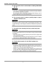
Improper installation or operation can result in serious injury or death.
Read user's manual and all warning labels before installation or operation.
Improper Installation or operation
can result in serious injury or
death. Read user's(owner's)
manual and all warning labels
before operation.
WARNING
■
Fig. 1-3 Warning label 3
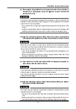
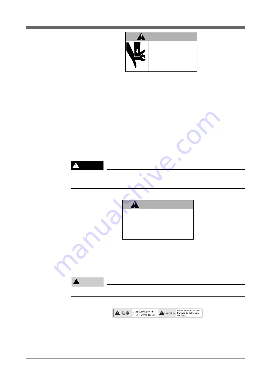
(4) Do not remove the Z-axis upper-end mechanical stopper
Removing or moving the upper-end mechanical stopper attached to the Z-
axis spline can damage the Z-axis ball screw. Never remove or move it.
!
CAUTION
Do not remove this part. Damage to the ball screw will result.
■
Fig. 1-4 Warning label 4
Summary of Contents for YK-X Series
Page 1: ...User s Manual ENGLISH E YAMAHA SCARA ROBOT E35 Ver 1 08 YK XG YK X series ...
Page 2: ......
Page 6: ...MEMO ...
Page 10: ...MEMO ...
Page 12: ...MEMO ...
Page 30: ...MEMO ...
Page 36: ...MEMO ...
Page 46: ...3 10 CHAPTER 3 Installation Ground symbol M4 Ground terminal Fig 3 6 Ground terminal ...
Page 78: ...3 42 MEMO ...
Page 80: ...MEMO ...
Page 101: ...4 21 CHAPTER 4 Adjustment Cover Elongated hole Y axis origin sensor stay Bolt Fig 4 8 a ...
Page 102: ...4 22 CHAPTER 4 Adjustment Dog Hex nut Fig 4 8 b Bolt Y axis arm X axis arm Fig 4 8 c ...
Page 119: ...4 39 CHAPTER 4 Adjustment R End effector End effector Z Y X Fig 4 18 ...
Page 120: ...4 40 MEMO ...
Page 122: ...MEMO ...
Page 138: ...5 16 CHAPTER 5 Periodic Inspection M6 16 M5 16 X axis motor Base Fig 5 3 ...
Page 146: ...5 24 CHAPTER 5 Periodic Inspection M3 16 M4 18 X axis arm Fig 5 10 ...
Page 155: ...5 33 CHAPTER 5 Periodic Inspection O ring r M5 14 M6 16 R axis motor Fig 5 17 ...
Page 156: ...5 34 CHAPTER 5 Periodic Inspection M3 14 M3 16 O ring w Fig 5 18 ...
Page 161: ...CHAPTER 6 Increasing the robot operating speed 1 Increasing the robot operating speed 6 1 ...
Page 162: ...MEMO ...
Page 168: ...6 6 MEMO ...
Page 170: ...MEMO ...
Page 177: ...MEMO ...


