


1-13
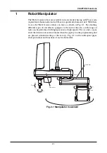
CHAPTER 1 Using the Robot Safely
8
Automatic Operation
Automatic operation described here includes all operations in AUTO mode.
(1) Check the following before starting automatic operation.
1. No one is within the safeguard enclosure.
2. The programming unit and tools are in their specified locations.
3. The alarm or error lamps on the robot and peripheral equipment do not
flash.
4. The safeguard enclosure is securely installed with safety interlocks ac-
tuated.
(2) Observe the following during automatic operation or in cases where an error
occurs.
1) After automatic operation has started, check the operation status and warn-
ing lamp to ensure that the robot is in automatic operation.
2) Never enter the safeguard enclosure during automatic operation.
3) If an error occurs in the robot or peripheral equipment, observe the fol-
lowing procedure before entering the safeguard enclosure.
1. Press the emergency stop button to set the robot to emergency stop.
2. Place a sign on the start switch, indicating that the robot is being in-
spected in order to keep any other person from touching the start switch
and restarting the robot.
9
Adjustment and Inspection
Do not attempt any installation, adjustment, inspection or maintenance unless it
is described in this manual.
10
Repair and Modification
Do not attempt any repair, parts replacement and modification unless described
in this manual. These works require technical knowledge and skill, and may also
involve work hazards.
Summary of Contents for YK-X Series
Page 1: ...User s Manual ENGLISH E YAMAHA SCARA ROBOT E35 Ver 1 08 YK XG YK X series ...
Page 2: ......
Page 6: ...MEMO ...
Page 10: ...MEMO ...
Page 12: ...MEMO ...
Page 30: ...MEMO ...
Page 36: ...MEMO ...
Page 46: ...3 10 CHAPTER 3 Installation Ground symbol M4 Ground terminal Fig 3 6 Ground terminal ...
Page 78: ...3 42 MEMO ...
Page 80: ...MEMO ...
Page 101: ...4 21 CHAPTER 4 Adjustment Cover Elongated hole Y axis origin sensor stay Bolt Fig 4 8 a ...
Page 102: ...4 22 CHAPTER 4 Adjustment Dog Hex nut Fig 4 8 b Bolt Y axis arm X axis arm Fig 4 8 c ...
Page 119: ...4 39 CHAPTER 4 Adjustment R End effector End effector Z Y X Fig 4 18 ...
Page 120: ...4 40 MEMO ...
Page 122: ...MEMO ...
Page 138: ...5 16 CHAPTER 5 Periodic Inspection M6 16 M5 16 X axis motor Base Fig 5 3 ...
Page 146: ...5 24 CHAPTER 5 Periodic Inspection M3 16 M4 18 X axis arm Fig 5 10 ...
Page 155: ...5 33 CHAPTER 5 Periodic Inspection O ring r M5 14 M6 16 R axis motor Fig 5 17 ...
Page 156: ...5 34 CHAPTER 5 Periodic Inspection M3 14 M3 16 O ring w Fig 5 18 ...
Page 161: ...CHAPTER 6 Increasing the robot operating speed 1 Increasing the robot operating speed 6 1 ...
Page 162: ...MEMO ...
Page 168: ...6 6 MEMO ...
Page 170: ...MEMO ...
Page 177: ...MEMO ...


