


3-2
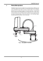
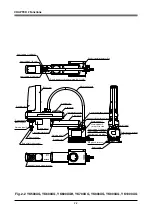
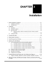
CHAPTER 3 Installation
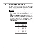
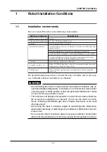
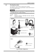
1-2
Installation base
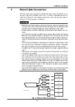
WARNING
• Install the robot on a horizontal surface, with the base mount section facing
down. If installed by other methods with the base mount section not facing
down, grease might leak from the reduction gear unit.
• Do not place the robot on a moving installation base. Excessive loads will be
applied to the robot arm by movement of the installation base, resulting in
damage to the robot.
!
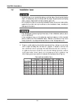
CAUTION
• The manipulator positioning might decrease if the installation surface preci-
sion is insufficient.
• If the installation base is not sufficiently rigid and stable or a thin metallic
plate is attached to the installation base, vibration (resonance) may occur
during operation, causing detrimental effects on the manipulator work.
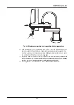
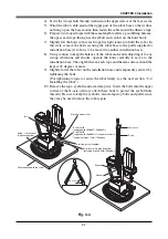
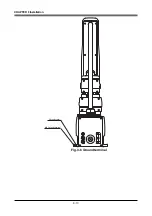
1) Prepare a sufficiently rigid and stable installation base, taking account of the
robot weight including the end effector (gripper), workpiece and reaction
force while the robot is operating. The maximum reaction force (see Fig. 3-
1) applied to the X-axis and Z-axis of each robot during operation is shown
in the table below. These values are an instantaneous force applied to the
robot during operation and do not indicate the maximum load capacity.
Robot Model
YK500XG
YK600XG
YK600XGH
YK700XG
YK800XG
YK900XG
YK1000XG
F
X
max
M
X
max
F
Z
max
The maximum reaction force
N
kgf
Nm
kgfm
N
kgf
1416
144
178
18
134
14
1476
150
178
18
134
14
2125
217
395
40
205
21
2479
253
395
40
239
24
2561
261
395
40
239
24
2494
254
395
40
165
17
2427
248
395
40
165
17
Summary of Contents for YK-X Series
Page 1: ...User s Manual ENGLISH E YAMAHA SCARA ROBOT E35 Ver 1 08 YK XG YK X series ...
Page 2: ......
Page 6: ...MEMO ...
Page 10: ...MEMO ...
Page 12: ...MEMO ...
Page 30: ...MEMO ...
Page 36: ...MEMO ...
Page 46: ...3 10 CHAPTER 3 Installation Ground symbol M4 Ground terminal Fig 3 6 Ground terminal ...
Page 78: ...3 42 MEMO ...
Page 80: ...MEMO ...
Page 101: ...4 21 CHAPTER 4 Adjustment Cover Elongated hole Y axis origin sensor stay Bolt Fig 4 8 a ...
Page 102: ...4 22 CHAPTER 4 Adjustment Dog Hex nut Fig 4 8 b Bolt Y axis arm X axis arm Fig 4 8 c ...
Page 119: ...4 39 CHAPTER 4 Adjustment R End effector End effector Z Y X Fig 4 18 ...
Page 120: ...4 40 MEMO ...
Page 122: ...MEMO ...
Page 138: ...5 16 CHAPTER 5 Periodic Inspection M6 16 M5 16 X axis motor Base Fig 5 3 ...
Page 146: ...5 24 CHAPTER 5 Periodic Inspection M3 16 M4 18 X axis arm Fig 5 10 ...
Page 155: ...5 33 CHAPTER 5 Periodic Inspection O ring r M5 14 M6 16 R axis motor Fig 5 17 ...
Page 156: ...5 34 CHAPTER 5 Periodic Inspection M3 14 M3 16 O ring w Fig 5 18 ...
Page 161: ...CHAPTER 6 Increasing the robot operating speed 1 Increasing the robot operating speed 6 1 ...
Page 162: ...MEMO ...
Page 168: ...6 6 MEMO ...
Page 170: ...MEMO ...
Page 177: ...MEMO ...


