


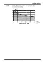
3-5
CHAPTER 3 Installation
2-2
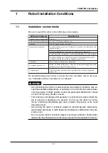
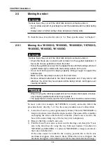
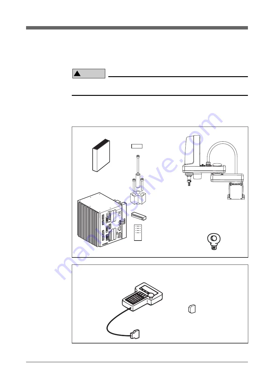
Checking the product
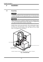
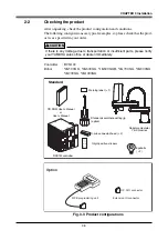
After unpacking, check the product configuration and conditions.
The following configurations are typical examples, so please check that the prod-
uct is as specified in your order.
!
CAUTION
If there is any damage due to transportation or insufficient parts, please notify
your YAMAHA sales office or dealer immediately.
Controller
: RCX142
Robot
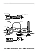
: YK500XG, YK600XG, YK600XGH, YK700XG, YK800XG,
YK900XG, YK1000XG
A B
X Y
Z R
RCX142
MOT
OR
XM
YM
ZM
RM
PWR
SRV
ERR
SAF
ETY
MPB
COM
STD
.DIO
RGE
N
ACIN
P
N
L
N
ROB
I/O
XY
ROB
I/O
ZR
OP.1
OP.3
OP.2
OP.4
200
-23
0V~
50-6
0Hz
MA
X.2
500
VA
MOD
EL.
SER
. NO
.
MAN
UFA
CTU
RED
FACT
ORY
AUT
OMA
TION
EQU
IPME
NT M
ADE
IN J
APAN
CA
UT
ION
REA
D INS
TRU
CTIO
N
MAN
UAL
BAT
T
ZR
XY
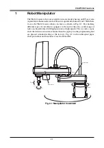
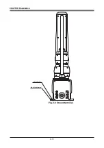
Robot manipulator
YK-XG series
CD-ROM User's Manual
or
User's Manual
RCX142controller
Warning label (
×
1)
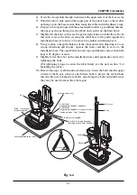
Standard coordinate setting jig
(option)
Eyebolts
(
×
2)
Origin position stickers
D-sub connector/hood (
×
2)
Standard
Option
MPB programming unit
Extension IO connector
OP, DIO connector
Fig. 3-3 Product configurations
Summary of Contents for YK-X Series
Page 1: ...User s Manual ENGLISH E YAMAHA SCARA ROBOT E35 Ver 1 08 YK XG YK X series ...
Page 2: ......
Page 6: ...MEMO ...
Page 10: ...MEMO ...
Page 12: ...MEMO ...
Page 30: ...MEMO ...
Page 36: ...MEMO ...
Page 46: ...3 10 CHAPTER 3 Installation Ground symbol M4 Ground terminal Fig 3 6 Ground terminal ...
Page 78: ...3 42 MEMO ...
Page 80: ...MEMO ...
Page 101: ...4 21 CHAPTER 4 Adjustment Cover Elongated hole Y axis origin sensor stay Bolt Fig 4 8 a ...
Page 102: ...4 22 CHAPTER 4 Adjustment Dog Hex nut Fig 4 8 b Bolt Y axis arm X axis arm Fig 4 8 c ...
Page 119: ...4 39 CHAPTER 4 Adjustment R End effector End effector Z Y X Fig 4 18 ...
Page 120: ...4 40 MEMO ...
Page 122: ...MEMO ...
Page 138: ...5 16 CHAPTER 5 Periodic Inspection M6 16 M5 16 X axis motor Base Fig 5 3 ...
Page 146: ...5 24 CHAPTER 5 Periodic Inspection M3 16 M4 18 X axis arm Fig 5 10 ...
Page 155: ...5 33 CHAPTER 5 Periodic Inspection O ring r M5 14 M6 16 R axis motor Fig 5 17 ...
Page 156: ...5 34 CHAPTER 5 Periodic Inspection M3 14 M3 16 O ring w Fig 5 18 ...
Page 161: ...CHAPTER 6 Increasing the robot operating speed 1 Increasing the robot operating speed 6 1 ...
Page 162: ...MEMO ...
Page 168: ...6 6 MEMO ...
Page 170: ...MEMO ...
Page 177: ...MEMO ...


